
Kordil Geodesy Tools User Manual
An advanced manual for coordinate transformations, parameter estimation and result checking, with interface explanations, examples and screenshots.
Open Web ManualDownload Turkish PDF
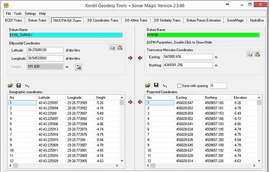
History of “Geodesy Tools” (“Kordil Geodesy Tools”)
Version 1, 2002
About Geodesy Tools, 2002 (Now Kordil Geodesy Tools)
This article explains the reasons for developing the first Geodesy Tools release in 2002 and describes its calculation tools. The aim was to combine coordinate and datum transformations with parameter estimation in a common workflow. Interfaces and functions may differ by software version.
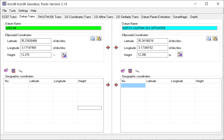
Kordil Geodesy Tools Modern, updated software interface.
- Consistent coordinate-system definitions and transformation parameters throughout a project help reduce discrepancies between calculation tools.
- Select tools according to the project's required transformation methods, data formats and accuracy objectives.
- General-purpose software designed to serve many users may not address specialised problems because of their limited market. A need can therefore arise for flexible software tailored to such tasks.
There are many further reasons for bringing calculation and transformation tools together, particularly familiar to surveying professionals. Some are illustrated below with specific examples.
- On a construction project using several datums, survey staff need a software package whose transformation workflow is easily understood by everyone. A single, straightforward package helps ensure that all staff transform coordinates correctly and consistently.
- Publicly available tools serve a broad range of users and offer many settings, datums, ellipsoids and projections. That is advantageous for general use, whereas a surveying project often needs only one projection and two ellipsoids or datum parameter sets.
- The software must be correctly configured each time it is used. A smaller but sufficient range of options can simplify long-term use for all users and reduce the risk of mistakes.
- Surveying software should read coordinate data in different formats, such as ID X Y Z, X Y Z or X Y, and let users verify that the chosen interpretation is correct.
- The package should also check known transformation parameters between two coordinate systems using known values and recalculate those parameters when necessary.
Many other industry-specific examples could be added. Geodesy Tools was developed as a specialised, extensible and easy-to-use package to address these needs.
BRIEF GUIDE TO THE GEODESY TOOLS TABS
[Datum Def] Datum Definition
This tab contains datum settings for transformations and calculations. Define, save and load datums here. Two datums can be used at once, with a single click switching between them. Saved or loaded definitions are restored automatically at the next start. Restricting accidental parameter changes helps reduce errors.

[ECEF Tr.] Earth-Centred Cartesian Coordinate Transformation
Converts ellipsoidal coordinates to Earth-centred, Earth-fixed coordinates (ECEF), also supplying input for Inv.DatumTr. Ellipsoidal angles can be converted between decimal degrees, degrees and minutes, and degrees, minutes and seconds. The green cells also allow coordinate format conversion with a single click.

[Datum Tr.] Datum Transformation
Transforms ellipsoidal geographic coordinates from one datum to another using the defined transformation parameters.

[(U)TM] Universal Transverse Mercator Projection
Performs (Universal) Transverse Mercator transformations using the defined datum. Projection parameters are stored on the right and can be changed by double-clicking. The latest settings are restored automatically next time.

Projection parameters are normally hidden to reduce accidental changes.

[XYZ Tr.] Transformation Between Earth-Centred Cartesian Systems
Transforms ECEF coordinates between datums. It can also transform 3D coordinates with a defined ellipsoid, using Euler angles for rotation rather than relying solely on a small-angle similarity approximation.

[Affine Tr.] Six-Parameter Affine Transformation
Performs a general six-parameter affine transformation in two dimensions. A single table can contain both source and target point coordinates and be reloaded as a transformation parameter file.

[Simil. Tr.] Four-Parameter Similarity Transformation
Performs a two-dimensional, four-parameter similarity (Helmert) transformation. A single table can contain both source and target coordinates and, as with affine transformation, be reloaded as a transformation parameter file.

[Inv.Datum.Tr.] Inverse Datum Transformation with Seven Unknowns
Uses industry-standard datum parameter estimation equations. Ellipsoidal coordinates cannot be entered directly but can be converted to ECEF using the software. This is also described as an inverse Helmert transformation using Euler angles. Initial rotation values in the adjustment are zero, so sufficiently large rotations may produce unreliable results. Geodesy Tools provides tools to check those results.

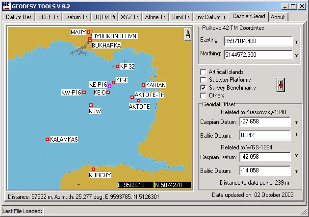
[CaspianGeoid] Caspian Sea Geoid
Contains an approximate geoid model developed for the Kashagan Field in the northern Caspian Sea. It is intended for regional value estimation and must not be used as a height reference for engineering surveys without verification at independent control points.
NOTES
Use this software at your own responsibility. Send comments and suggestions to the stated email address. No obligations are imposed on users provided each user downloads it from the same website on which it is published.
Inspect the sample data in the program folder to understand how Geodesy Tools reads file formats.
Coordinate direction letters are not accepted as input; use + and − signs instead. For example, 46 S is not recognised, whereas -46 is accepted. Similarly, use 55W instead of -55 as the numeric value.
Parameter estimation uses least squares. Residuals, control point distribution and independent check points must be examined together. Clearly define source and target datums, coordinate order, units, projection and, where relevant, coordinate epoch.
REFERENCES
[1] Demirel, H., Indirect Observation Adjustment, lecture notes, Yıldız Technical University, Department of Geodesy and Photogrammetry Engineering, Geodesy Division, Istanbul, 1994.
[2] WGS 84 Implementation Manual, EUROCONTROL European Organization for the Safety of Air Navigation, Brussels, Belgium, and IfEN Institute of Geodesy and Navigation (IfEN), University FAF Munich, Germany, Version 2.4, 12 February 1998.
[3] Geocentric Datum of Australia Technical Manual, Intergovernmental Committee on Surveying & Mapping, Version 2.2, February 2002.
[4] Coordinate Conversions and Transformations Including Formulas, European Petroleum Survey Group (EPSG), Version 19, December 2002.
[5] Land Information New Zealand, Geodetic System Technical Report, Recommended Transformation Parameters from WGS84 to NZGD49, 9 March 1999, revision date 22 August 1997.
[6] Young-Hoo Kwon, Rotation Matrix; Axis Rotation Matrices – Axis Rotation vs. Vector Rotation, Orientation Angles; Eulerian/Cardanian Angles – Computation of Orientation Angles, 1998.
[7] POSC, Epicentre Usage Guide, Geographic Coordinate System Transformations, POSC Specifications, Version 2.2, 13 September 2000.
ACKNOWLEDGEMENTS
I would like to thank the colleagues who supported the development of this program from the beginning: Erol Türk, Civil Engineer, Bechtel–Enka JV, and Muzaffer Şahin, Electrical and Electronics Technician, Bechtel–Enka JV.
Harun Karaman