
Kordil Bathymetry Studio (KBS) User Manual
Updated KBS User Manual
A 16-section field guide in Turkish covering setup, coordinate systems, GNSS and SBES connections, multiple sensors and targets, NTRIP, sound velocity profiles, logging and troubleshooting.
Search the manual, enlarge screenshots or use the print option to save a PDF.
Previous Version 5 Manual — Archive
Kordil Bathymetry Studio User Manual
Contents
1.1 What Is Kordil Bathymetry Studio (KBS)?
2.3 Settings and Geodetic Parameters
2.3.2 Sensor or Single-Beam Echo Sounder (SBES) Settings Window
2.4 Offsets Required for Bathymetric Surveying
2.8 Importing Background Maps and Survey Lines
3.4 Transverse Mercator / Gauss–Krüger / Universal Transverse Mercator Transformation
3.5 3D Coordinates / ECEF Transformation
4 Kordil Bathymetry Studio Single-Beam Editor
5 Installing Kordil Bathymetry Studio
5.1.1 Date, Time and Number Format Settings
5.1.2 Administrative Privilege Settings for Programs
Kordil Bathymetry Studio
What Is Kordil Bathymetry Studio (KBS)?
Kordil Bathymetry Studio (KBS) is a software suite combining navigation, data recording, coordinate and datum transformation, CAD data exchange and depth-data processing for bathymetric survey workflows. This manual covers version 5; menus, licensing and supported instruments may differ in current versions.
KBS Components
KBS comprises the following components and software packages.
1 – Kordil Navigation Pro
2 – Kordil Geodesy Tools
3 – SonarMagic
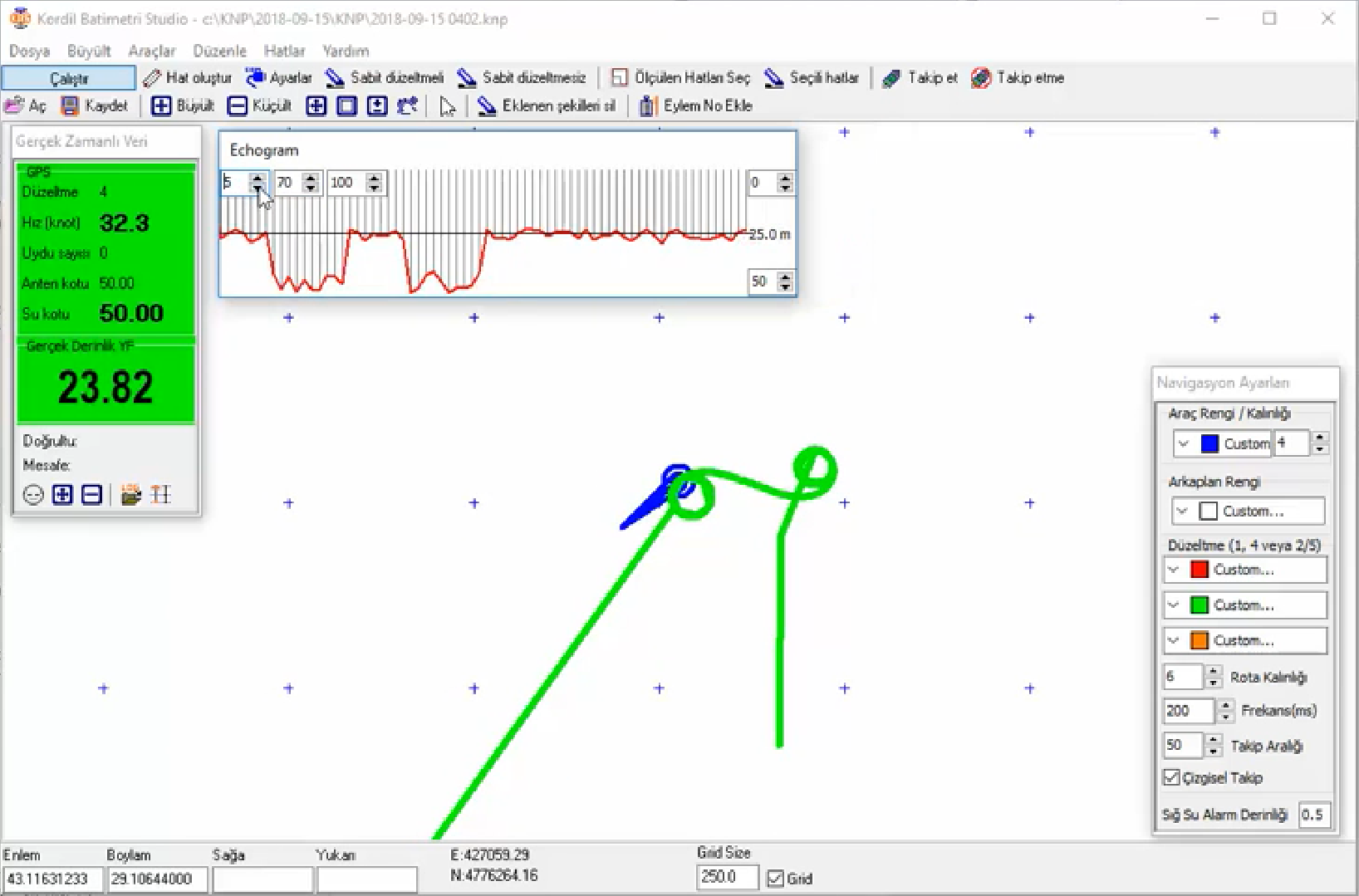
Kordil Navigation Pro (KNP)
Kordil Navigation Pro is the navigation and data-recording component of KBS. When connecting GNSS receivers and other sensors, check supported message types, serial settings, time alignment and data formats. Do not assume every instrument producing NMEA-like output is directly compatible.
Navigation Settings
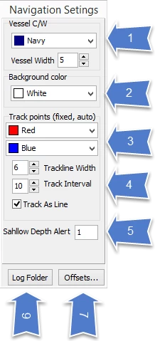
1 – Change the colour and line thickness of the survey craft on screen.
2 – Select the screen background colour.
3 – Track colours can be selected according to positioning quality. In the adjacent example, red denotes low-quality autonomous data without corrections.
4 – Set the colour and thickness of the vessel track. The track interval determines how often consecutive positions are joined. Higher values improve performance but reduce display resolution. Tests over a full survey day suggested a value of 10 for 1 Hz positioning data. This setting affects the display only, not recording or raw data; use a reasonably high value.
5 – Shallow Depth Alert warns of shallow water during surveying. If the observed depth is less than the selected threshold, the background turns red to indicate an alarm.
6 – Log Folder opens the folder containing all recorded data.
7 – Offsets opens a window for entering all survey offsets. Every required field must be completed correctly, fully and precisely.
Pop-up Windows
Unlicensed software opens in demo mode and permits only two minutes of online operation.

The following window appears and disappears automatically when the software starts. It indicates whether GPS and other devices are connected.

Settings and Geodetic Parameters
The windows are introduced in sequence below.
GPS Settings Window
Change the required GPS parameters here. If an external heading sensor is available, the “Enable Gyro” option can also be used.

Sensor or Single-Beam Echo Sounder (SBES) Settings Window
Configure the NMEA sensor, such as the single-beam echo sounder, on the tab shown. After entering the settings, ensure “Sensor Enable” is checked.

Geodetic Parameters
Define datum and projection parameters on this tab. Before surveying, verify source and target coordinate systems, units, zones and transformation parameters using known control points. Continued raw-data recording does not remove the effects of incorrect geodetic settings on displayed positions or processed outputs.


Offsets Required for Bathymetric Surveying
Enter essential bathymetric survey offsets and those needed for troubleshooting in the table below. Some values may appear unnecessary but can prove vital when recovering data. Enter offsets before surveying to maintain a complete dataset. These values are used temporarily to display corrected depths during surveying; they do not affect the recorded raw data. They can be entered again or corrected during office processing.

Survey Craft Geometry
The on-screen survey craft symbol is important when following survey lines. Adjustable options allow its shape to suit the working scale. Use the following window to configure it.
In the illustration below, in order:
- Radius of the first circle
- Parallel distance to the second circle
- Number of circles
- Arrow width to the right and left
- Arrow length

The default values were found suitable for single-beam bathymetry at 1:1000 scale, with survey lines spaced 10 m apart.
Apply and save settings using the button below. Changes become visible only after restarting the software.
Bathymetric Surveying
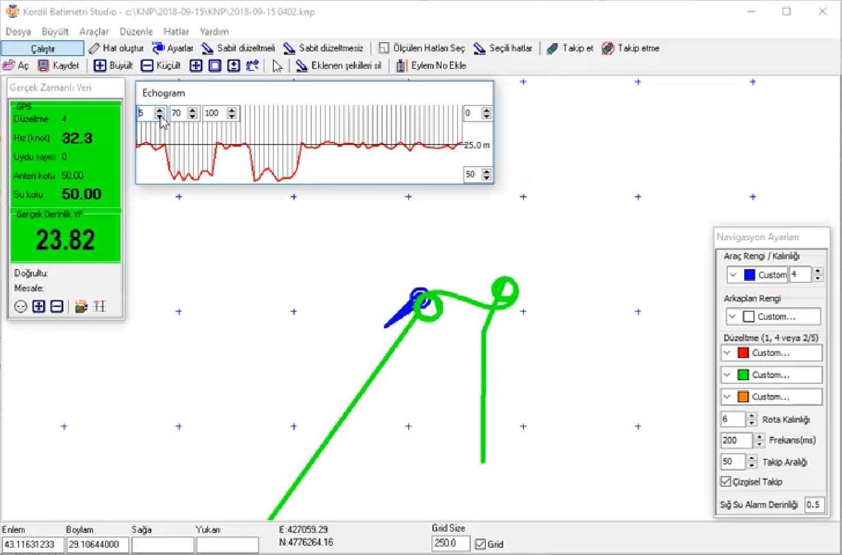
Some icons are enabled in offline mode and others are disabled. Drawing, for example, is unavailable online. The illustration below shows offline mode on the left and online mode on the right.
Icon Menu
The following icons are available. Commonly used icons are explained in order below.
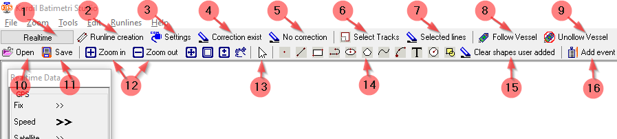
- Real-time surveying can begin once all connections have been established.
- Creates lines between two points and parallel to them.
- The Settings menu contains GPS and NMEA sensor connection settings and geodetic parameters.
- Deletes FIX tracks.
- Deletes FLOAT tracks.
- Selects tracks.
- Deletes tracks within the selected area.
- Follow is selected by default. The survey craft stays at the centre of the screen while the background map moves.
- No Follow keeps the background map fixed while the craft moves. This option is useful when inspecting another part of the display.
- Load KNP files here. The current drawing disappears from the screen, with a copy retained under C:\KNP.
- Saves the current background map, survey lines, tracks and craft symbol in “C:\KBP\YYYY-MM-DD\YYYY-MM-DD.knp”.
- Zoom in or out by changing the window size. F2 and F3 are the zoom keyboard shortcuts.
- Selects objects on screen. While following survey lines, it can highlight the active line with a thicker stroke; selected objects can also be deleted.
- Basic drawing tools operated with the mouse
- Clears all user-added objects.
- Assigns an event number to the current position and records it with details in the Event Log file.
Importing Background Maps and Survey Lines
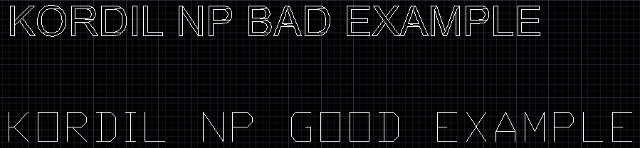
Use Import under the File menu to load DXF background maps. Supported objects include lines, polylines and arcs compatible with AutoCAD R12. Text can be loaded after exploding it with TXTEXP in AutoCAD. To avoid unnecessary lines generated by exploding text, first change all text objects to txt.shx. The AutoCAD example below illustrates the difference: Arial above and TXT below.
Event Mark
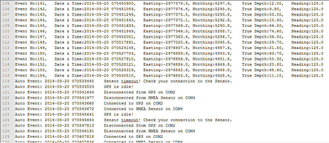
Sequential event numbers are assigned automatically, and the following details recorded in the Event Log. This is useful for manual sounding or echo sounder calibration. Fixed objects at sea, such as buoys, can also be marked on screen, with details saved in the Log Folder for later use.
Kordil Geodesy Tools
Kordil Geodesy Tools includes coordinate and datum transformation, error detection and parameter calculation tools, together with processing steps for GPS, single-beam echo sounder and other sensor data acquired with Kordil Navigation Pro. The program uses ASCII text files and detects their format automatically. Geographic coordinates must be in DMS, decimal degrees or DM format.
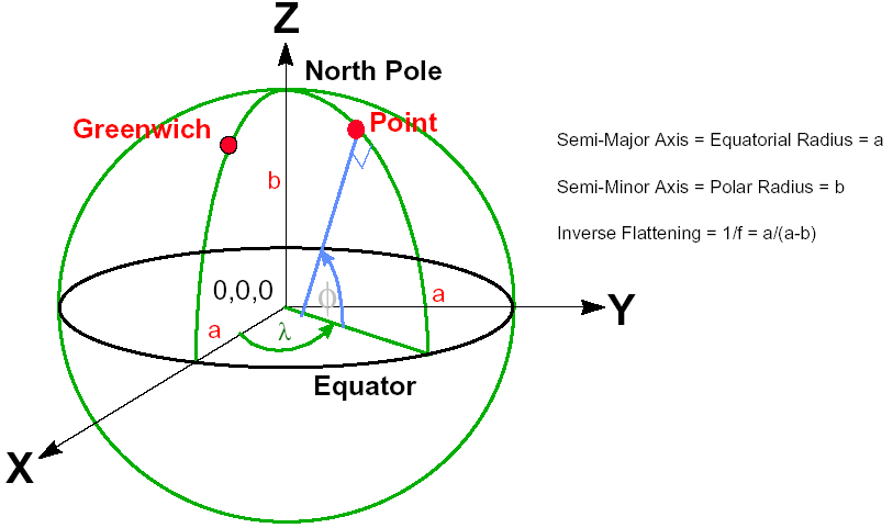
World Coordinate System
Kordil GT uses a minus sign for southern latitudes and western longitudes. Letters are not recognised in the coordinate conversion cells; use a minus sign instead.
Kordil GT uses a minus sign for southern latitudes and western longitudes. Letters are not recognised in the coordinate conversion cells; use a minus sign instead.
Datum Transformation
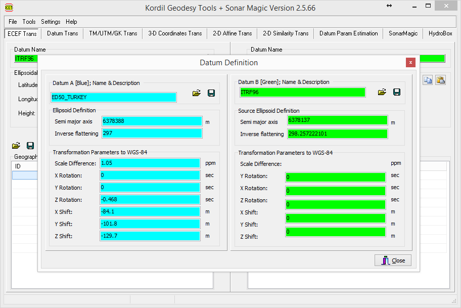
KGT uses two parameter sets for transformation. If a different datum set is needed, load and select the new parameter set before transforming.
ECEF Transformation
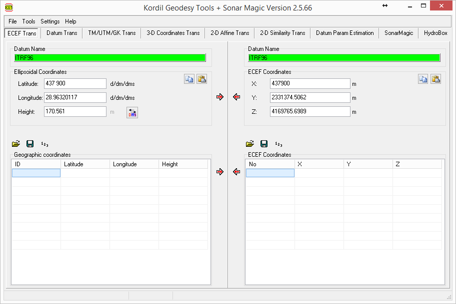
ECEF transformation uses an ellipsoid-based, three-dimensional Earth-centred, Earth-fixed Cartesian coordinate system. It is used for transformations between datums, such as WGS 84 and ED50.
Datum Transformation
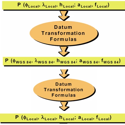
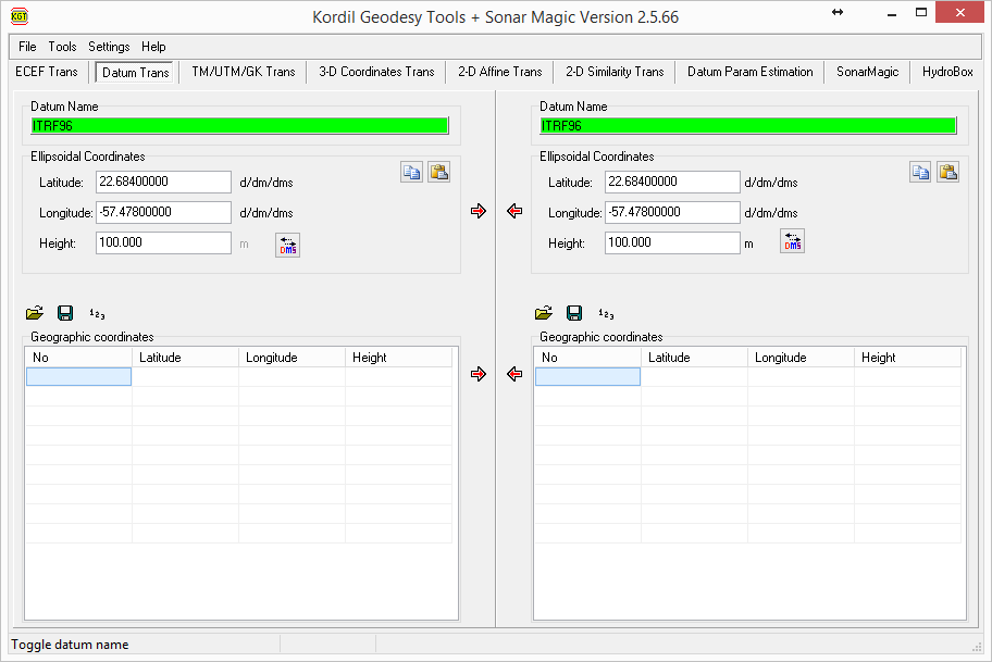
As with ECEF transformation, datum transformations can be performed between geographic coordinates. The diagram below shows the same region referenced to two ellipsoids and the transformation steps used by Geodesy Tools.

Transverse Mercator / Gauss–Krüger / Universal Transverse Mercator Transformation
This is the suite's most frequently used tool, allowing conversion between TM coordinates and geodetic coordinates in the same or another datum. SonarMagic also uses this step when processing GPS data expressed as latitude and longitude.
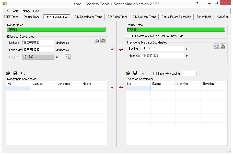
UTM/TM/GK parameters can be set in the panel on the right. Double-click to open or close it.

3D Coordinates / ECEF Transformation
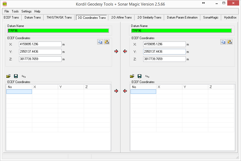
This section transforms ECEF coordinates from one datum to another. XYZ coordinates can also be transformed between systems using seven Bursa–Wolf parameters. It operates with ellipsoidal coordinates through the geocentric, Earth-fixed Cartesian system (XYZ).
Affine Transformation
A two-dimensional affine transformation uses six parameters. The illustration below shows the software interface. It is commonly used to transform processed coordinates when axes and scales differ and for photogrammetric image rectification. At least three control points known in both systems are required.
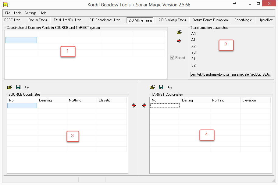
1 – Control points defined in both systems.
2 – Calculate the transformation parameters. A report is generated with the first calculation.
3 – Load source-system points to transform them into the target coordinate system.
4 – Load target-system points to transform them back into the source coordinate system.
Transformation Matrix:

XT, YT (target): coordinates of point P in the target coordinate reference system;
XS, YS (source): coordinates of point P in the source coordinate system.
Calculation details are displayed in an editor to detect errors and assess parameter quality. Calculated parameters remain there until the next calculation. To view the details report selected by the checkbox, first press Calculate in the menu, as shown in the first illustration below.
Similarity Transformation
The interface resembles the affine transformation interface. Four transformation parameters are used, requiring at least two control points known in both systems.
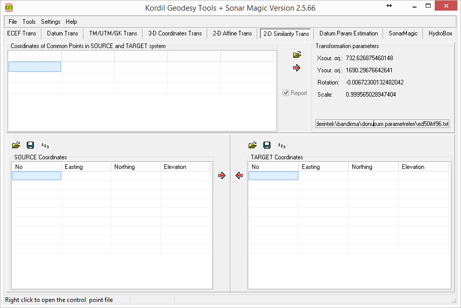
A two-dimensional similarity transformation (planar Helmert transformation) uses four parameters. A single scale factor is applied consistently in both axes to match the target system. A coordinate table can contain both control points and points to be transformed. As with affine transformation, the same file can be loaded as a transformation parameter set.
Transformation Matrix [4]:

XT, YT (target): coordinates of point P in the target coordinate system;
XS, YS (source): coordinates of point P in the source coordinate system.
1+dS = one unit of length in the source coordinate system, expressed in target-system units;
q = the angle through which the source-system axes are rotated to coincide with the target-system axes.
Calculation details are displayed in an editor to detect errors and assess parameter quality. Calculated parameters remain there until the next calculation. To view the details report selected by the checkbox, first press Calculate in the menu, as shown in the first illustration below.
Parameter Estimation
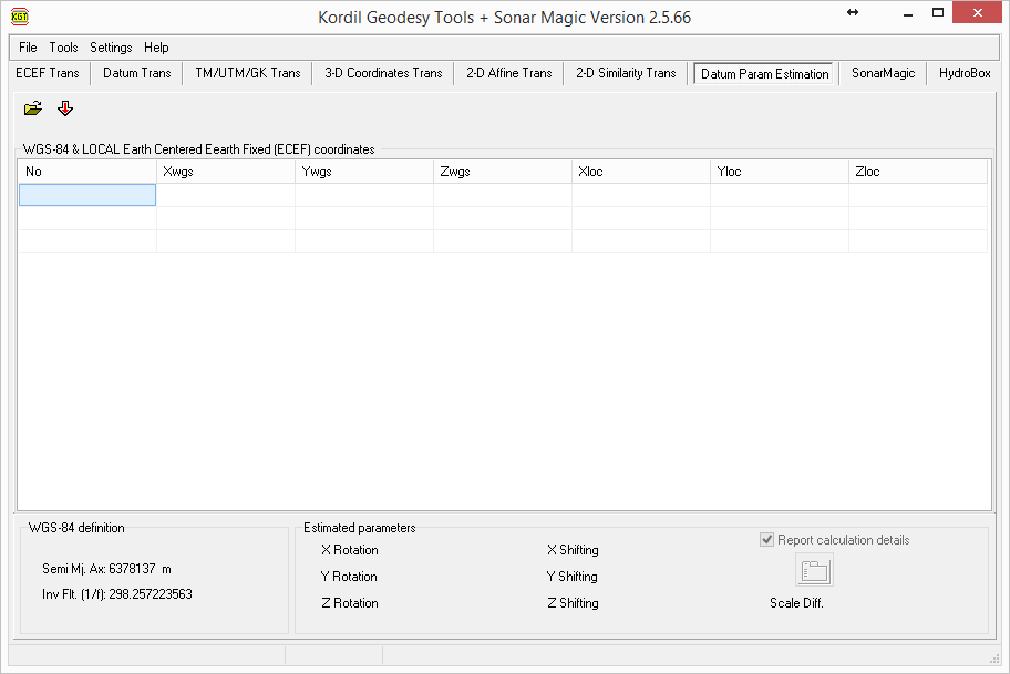
This section uses estimation equations to determine datum parameters. It estimates the seven parameters of a three-dimensional Helmert transformation, also described here as an inverse Helmert or Bursa–Wolf transformation. Translations and rotation angles are estimated by inversion of the equations below. The small-angle form assumes rotations are very small and expressed in radians. Geodesy Tools uses Euler angles for estimating the datum transformation parameters.
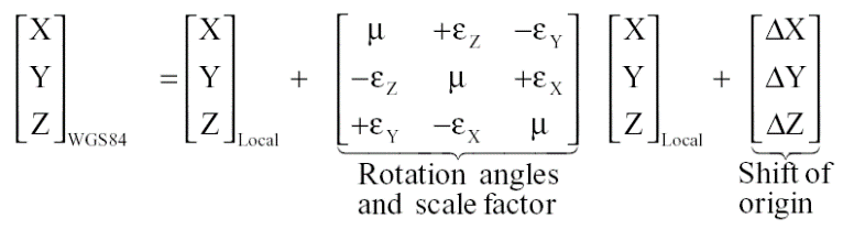
Geodesy Tools uses a rotation matrix based on orientation angles – Euler/Cardan angles [5].

After the user loads the parameters and runs the calculation, the results appear in this section. If the checkbox shown in the second image 
SonarMagic
The final processing step combines GPS and NMEA sensor data. This tool was designed particularly for single-beam bathymetric processing, but can also be used with other NMEA sensors. Key elements are numbered in the image and explained below.
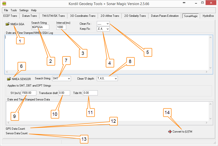
- Load the NMEA GGA GPS file from the Kordil Navigation Pro log.
- Extract GGA messages from the incoming GPS data. If several message types were recorded, this filter selects the required GGA messages.
- The NMEA GGA message interval is entered in milliseconds; one second is commonly used. For messages every five seconds, enter 5000; for two messages per second, enter 500. A GPS output of 1 Hz and an interval of 1000 ms are recommended here.
- Users can retain only FIX data and remove the remainder.
The GGA quality field identifies positioning status numerically. Manufacturer implementations can differ. In the systems described here, 4 denotes RTK FIX; confirm the meaning against the receiver documentation and the applicable NMEA version. To retain only the required status, enter its value and press Keep Fix. For DGPS records, the value would be 2, retaining only DGPS data.
1: Autonomous
2: DGPS
3: Used in different ways; generally indicates no solution or FLOAT.
4: RTK FIX on all GPS receivers tested by Kordil.
5: Usually RTK FLOAT; 3 is sometimes used instead.
- Remove unwanted position statuses from the GGA data. Here, “,,,,,” indicates that no coordinates are yet available and the record may be deleted.
- Load echo sounder (SBES) data here.
- SMT is a Kordil-specific format. Its message structure is shown below.
$SDSMT: Message format
- 1: Echo sounder number
- 0.99: Depth
- 13.1: Battery voltage
- 92: Quality indicator (20–150; higher values indicate better measurement quality)
- 0*78: Checksum
In addition to SMT, NMEA DBT and DTP messages can be loaded and processed directly here. These message types can be selected on many echo sounders. For other formats, processing can be performed manually in Microsoft Excel ® instead of automatically.
- Enter a characteristic text string here to delete matching records. This is commonly used to remove zero depths output by echo sounders when they fail to resolve the bottom. Entering T,1,0, or T,1,0.00, removes faulty zero-depth SMT records. The 1 between commas is the echo sounder ID.
- Enter the sound-velocity correction value for SBES processing here.
- Enter the submerged transducer offset; it is applied to every depth. Some sounders allow this offset to be entered in the instrument itself. In that case, enter zero here.
- Enter the water-level elevation recorded during the survey to reference depths to a datum. A single value is insufficient if water levels vary substantially. In that case, process the data manually in Excel and apply hourly or minute-by-minute water levels.
- The number of GPS records is displayed after loading. Reductions caused by the cleaning steps in stages four and five can be monitored and assessed here.
- As in stage twelve, the reduction in records after cleaning in stage eight can be assessed here.
- GPS and SBES data are transferred to the TM transformation window for final coordinate conversion. A new CSV file is then created in the log folder. Many subsequent operations can also be performed on this file in Excel.
HydroBox
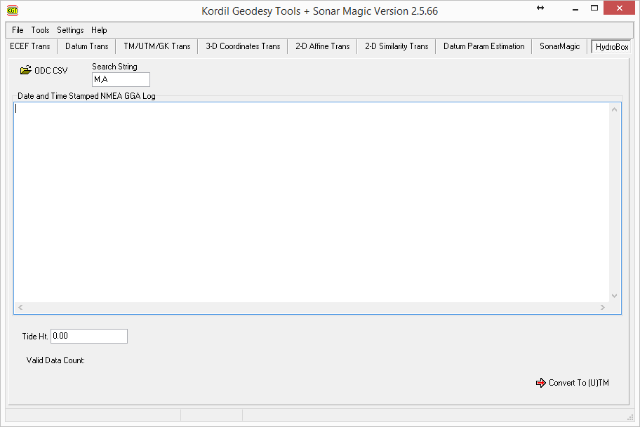
Converts HydroBox CSV files to XYZ and applies the required water-level correction.
Kordil Bathymetry Studio Single-Beam Editor
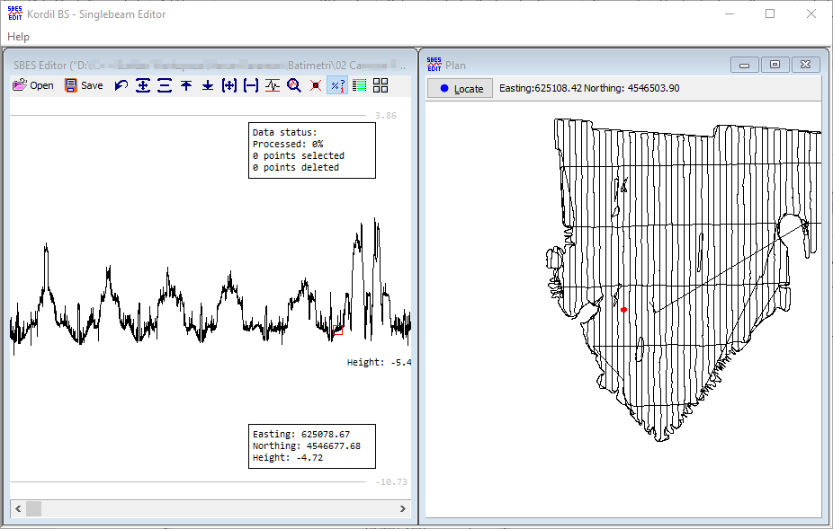
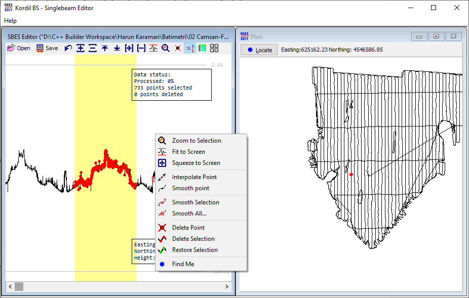
Kordil BS – Single-Beam Editor is the data-processing application supplied with Kordil BS. It supports the following edits:
- Interpolation of a single point,
- smoothing of a single point,
- smoothing of multiple points,
- smoothing of the entire terrain dataset,
- deleting or restoring points.
Locate the cursor position in either profile or plan view. In profile view, right-click and select Find me to locate it in plan view. In plan view, select a point and press Locateto display the point in profile.
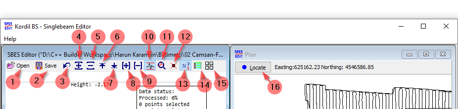
- Open: Selects and loads an XYZ file.
- Save: Saves the current data to an XYZ file.
- Undo: Restores the data to the state before the last action.
- Grow vertically: Applies vertical exaggeration for display only; elevation values are unchanged.
- Squeeze vertically: Compresses the display vertically without changing elevation data.
- Push up: Shifts the terrain display upwards without changing elevation data.
- Push down: Shifts the terrain display downwards without changing elevation data.
- Grow horizontally: Expands the display horizontally without changing distances between points.
- Squeeze horizontally: Compresses the display horizontally without changing distances between points.
- Toggle Fit to Screen: Automatically fits the terrain to the screen when checked.
- Zoom to Selection: Expands the selected region horizontally to fill the screen.
- Show Deleted Points: Displays deleted points when checked.
- Show Data Status: Displays data information at the upper right when checked.
- Settings: File Format Identifier, Smoothing Factor, Maximum Smoothing Distance, Line Thickness and Color Configuration.
- Change Orientation: Changes the arrangement of the windows.
- Locate: Moves the profile display to the point selected in plan view.
Additional Features:

Installing Kordil Bathymetry Studio
The archived version was intended preferably for Windows 7 or Windows 8 and was also tested on Windows XP.
Opening the Window
To run KBS correctly, the following settings must be configured before starting the software. These generally concern Windows regional and character settings.
Date, Time and Number Format Settings
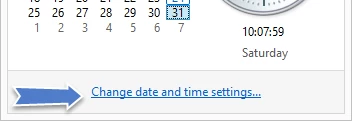
Move the pointer to the clock showing “10:07” and left-click once.

Click “Change date and time settings…”
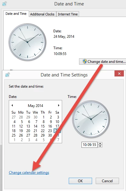
Click “Change date and time…” and then open “Change calendar settings…”.
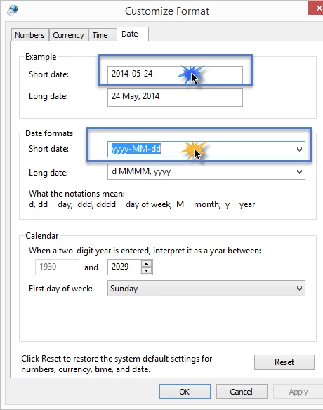
Set the short date format as shown below.
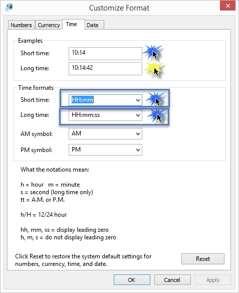
Select the Time tab and make the changes shown in the following images.
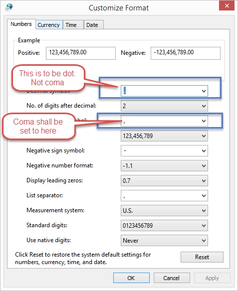
Set the decimal point and comma in the fields shown below.
Administrative Privilege Settings for Programs
KBS and KGT can run with administrator privileges. Without sufficient permissions, they may be unable to write settings beside the executable or INI file. The following options describe launching with elevated privileges or setting this behaviour in the compatibility properties.
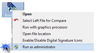
- – Right-click the program icon and select “Run as administrator”.
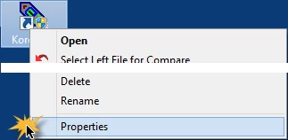
- – Right-click the program icon, choose Properties, open Compatibility and enable “Run this program as an administrator” to apply the setting to subsequent starts.

Installation
A setup wizard guides you through the installation.
Licensing the Software
Each installation requires a licence key. Open Help / About and send Kordil the displayed code, consisting of seven groups of numbers, to obtain a valid key. Enter the key in the dark field shown and press Register. Once accepted, the registration button is disabled and the registration dialog can no longer be edited.

Computer Clock
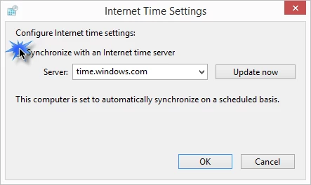
KNP uses GPS time and the computer settings. When connecting to the internet during a survey, the archived workflow requires automatic clock synchronisation to be disabled because the computer may otherwise return to local time and apparent data errors can result. The data are not necessarily lost, but additional processing may be required.
Common Problems
The following issues have been encountered in practice, together with possible solutions.
- If KNP receives no GPS or SBES data, check the COM ports with HyperTerminal or TeraTerm. Some ports may need to be activated. Once valid data and the message stream are confirmed in the terminal emulator, check reception again in KNP.
- If data are received but the background map or craft symbol does not appear, check the computer clock settings described above.
- If changes are not reflected immediately, restart the software after adjusting settings such as Global Parameters or Vessel Shape.
- If an imported DXF is not visible at the current location, its coordinate system may differ from the working coordinate system.
- If the craft continues to point north while moving, ensure Tools / Settings / Enable Gyro is not selected unless an appropriate heading input is connected.