Kordil EPS® & CPS
Integrated User Manual
From machine to project, from measurement to safe operation.
A field guide covering hardware and software together for excavator operators, crane operators and marine construction teams.
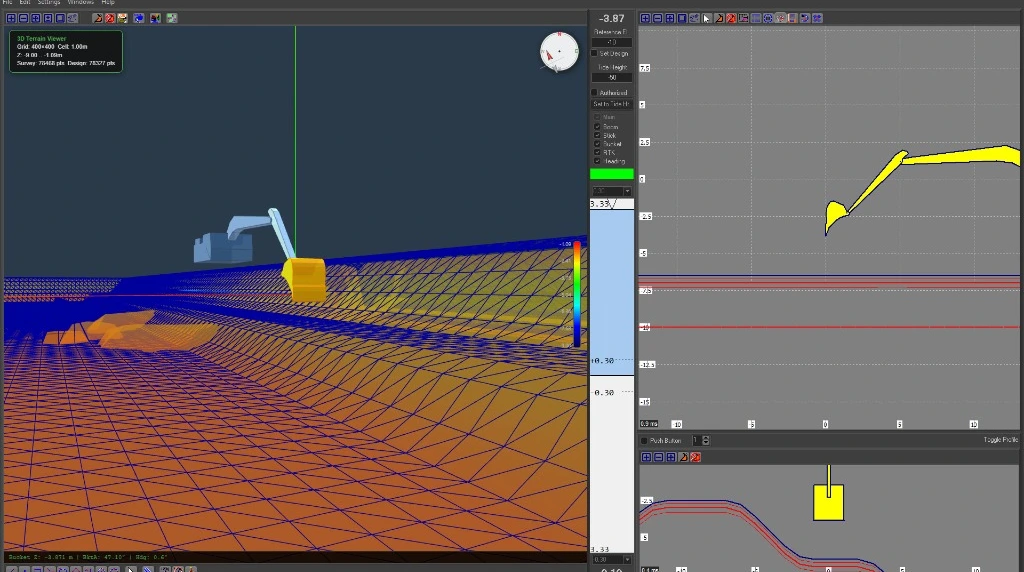 123
- 1 3D working area and machine position relative to the model.
- 2 Longitudinal/side view: reach and working elevation.
- 3 Transverse/front-rear view: lateral position and relationship to the profile.
Contents
- Scope and quick start
- Safe operation
- EPS / CPS system family
- Hardware and sensors
- Roles and authority
- Installation and commissioning
- Coordinates, elevations and water level
- Project and data import
- Reading the displays
- Working with an excavator
- Crane and free-fall grab
- Marking and recording
- Testing and calibration
- Acceptance and quality control
- Difference map and 3D
- Maintenance and change management
- Do's and don'ts
- Troubleshooting
- Field checklists
- Terms and frequently asked questions
- Version and sources
Correct data. Correct machine. Correct reference.
This manual describes the integrated workflow for Kordil EPS — Excavator Positioning System and Kordil CPS — Crane Positioning System from preparing a job to end-of-shift handover. As well as software displays, the system includes GNSS, motion sensors, rope-length measurement and the hardware fitted to the machine.
All main components of Kordil EPS/CPS are developed by Kordil and supplied as an integrated solution. Kordil H4 GNSS, Kordil motion-sensing and sensor-interface solutions, EPS/CPS software and field integration form this integrated system. Kordil OEM computer and display solutions are selected to suit the installation package. This does not mean that the excavator or crane itself, the operating system or every electronic subcomponent is manufactured by Kordil.
Operators: chapters 2, 8–12 and 17–19. Installation personnel: 4–7, 13–14 and 16. Survey/project leads: 7–8, 12 and 14–15. Screen names are given with their English equivalents to make them easier to find across installations.
Eight steps at the start of a shift
- Inspect the working area, machine and cable/sensor connections from a safe position.
- Open the approved machine configuration and the correct job/project file.
- Check the GNSS solution, heading and freshness of all required sensor data.
- Verify the active design and existing surface, including their revisions.
- Check the horizontal coordinate system, vertical reference and any water-level correction.
- Perform an independent position/elevation check at a known control point.
- Take a mark at a safe test point and confirm that it appears in the log file.
- Start work in the correct recording mode. If a problem occurs, stop and diagnose it rather than continuing.
Installation packages and software versions may not contain identical displays or all options. An option described here is not necessarily enabled on every machine. The site-specific handover and acceptance documentation takes precedence.
A guidance system does not replace a safety system
The operator is responsible for machine movements and must work with the site signaller, lifting supervisor and safety procedures. Empty space on the display does not prove that the real working area is free of obstacles.
- Never stand under a suspended load or bucket. Secure the machine before installation, checks or cleaning; isolate energy sources where necessary.
- Do not climb onto an operating machine to reach sensors, antennas or cables. Follow the rules for working at height, working over water and fall protection.
- Do not approach power lines, pipelines, structures or exclusion zones using the display alone. Approved safety distances and a spotter are required.
- Stop precision work if positions or elevations jump, data freeze, GNSS is invalid, a sensor disconnects or the design may be incorrect.
- Records generated from bucket contact do not automatically replace independent hydrographic surveying or final acceptance measurements.
Conditions requiring work to stop
An unverifiable reference; displaced antenna/sensor; an unverified bucket change; unexpected rope slack or swing; stale data; a check measurement outside acceptance limits; or work outside the design coverage. Move to a safe state, note the log time, notify the responsible team and do not resume precision work until revalidation is complete.
How do EPS and CPS relate to each other?
Kordil EPS
Relates the excavator body, boom, stick and bucket geometry to position, heading and motion measurements. The operator compares the working tip with the design surface and sections.
Kordil CPS
In crane applications, tracks a configured working point using measurements such as machine position, boom angle and rope payout. It gives operators a project reference for filling, placement, installation and marine construction.
Both solutions share the same principle: approved project + correct machine geometry + current measurements + verified reference. The excavator relies on its articulated linkage; the crane on the boom and suspension arrangement. The same “bucket elevation” label may represent a different physical reference in different setups. The measured point must be clearly defined in the acceptance documentation.
| Working arrangement | Primary monitoring | Specific checks |
|---|---|---|
| Hydraulic excavator | Body/heading, boom, stick, bucket and tip position | Bucket tooth, pin geometry and sensor orientation |
| Crane / CPS | Position, heading, boom and rope/suspension arrangement | Defined load/working point; actual suspension geometry |
| Free-fall grab / winch | Crane-suspended grab, rope length and defined reference | Slack rope, swing, bottom contact and settling after the drop |
| Floating platform | The above plus platform and reference conditions | Verify water level, motion and the conversion to project elevations |
Machine options such as “Is an excavator”, “Is a lifting crane”, “Is a winch dredger” and “Is a gravity graber” are not interchangeable. In particular, the profile for a free-fall arrangement must be selected by Kordil installation personnel. Never change the machine type merely to make its graphic look right.
Main components on the machine
Treat hardware as a physical part of the measurement chain, not merely an icon on screen. A loose bracket, displaced antenna or crushed sensor cable can cause an error at the working tip. The number and arrangement of components vary by machine.
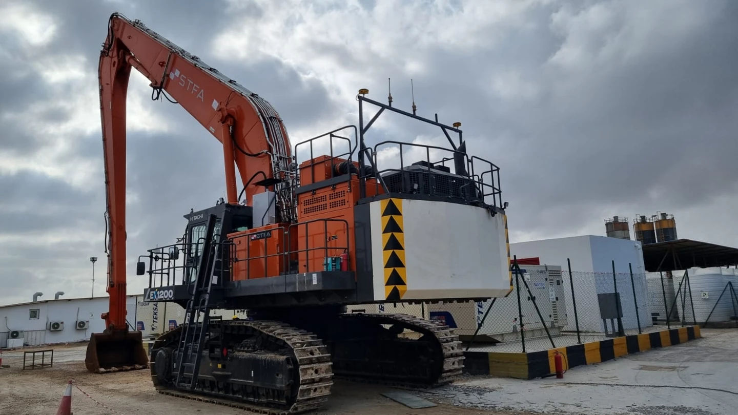 1234
- 1 Boom: the main member rising from the machine body.
- 2 Arm / stick: the second member extending towards the bucket.
- 3 Bucket: the bucket and its ground-contacting working tip.
- 4 Antenna support on the upper structure.
4.1 Boom, stick and bucket sensors
The boom sensor monitors the attitude of the main boom; the stick sensor monitors the attitude of the second member; the bucket sensor helps monitor bucket orientation. Systems with a body sensor also account for machine tilt. Together with the approved machine geometry, these measurements determine the working point. Data appearing on screen do not alone prove that a sensor is physically mounted correctly.
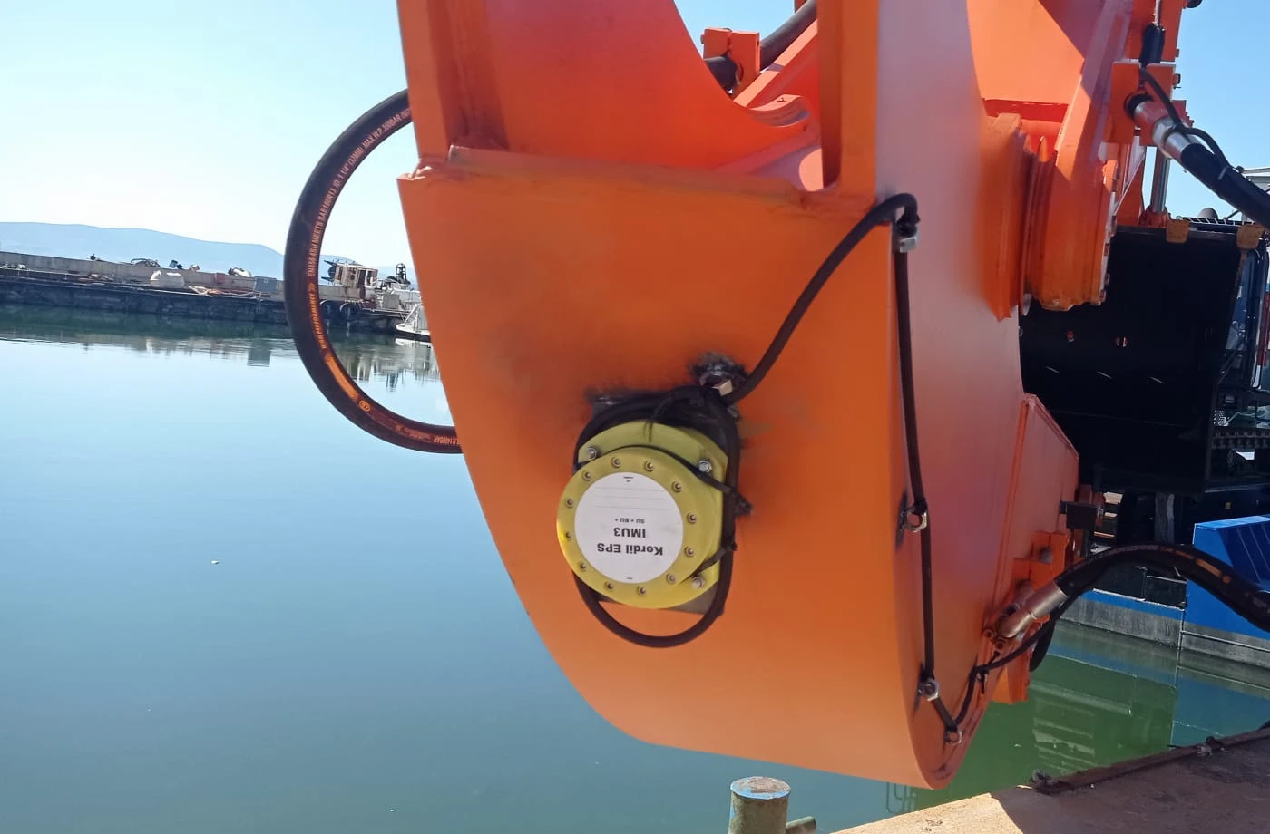 12
- 1 Kordil IMU sensor housing shown in the photograph.
- 2 External cable and fixing area: check for impact, breakage and abrasion.
This close-up identifies the sensor's exterior. Confirm boom/stick/bucket channel assignments from the installation record, not from the photograph alone. Mounting angle, internal connections and proprietary communication details are outside this manual's scope.
Kordil field archive, 2026; unrelated personnel have been cropped out.| Component | Operator checks | Authorised team checks |
|---|---|---|
| Boom / stick sensor | Damage to housing, bracket and visible cable; continuous movement on screen | Channel assignment, mounting direction and checks at reference positions |
| Bucket sensor / tip model | Bucket replacement, tooth wear, impact and abnormal orientation | Tip/pin reference, geometric profile and calibration for the new attachment |
| Body and heading sensing | Consistent display heading as the machine rotates | Body reference, heading correction and verification of the antenna/linkage relationship |
| GNSS antennas | Clear sky view, loose support, cable condition and water ingress | Antenna definition, offsets, heading reference and solution quality |
| Z sensor / rope length | Smooth change during lowering/lifting; sudden jumps or frozen data | Scale, direction, verification at known lengths and suitability for the pulley/rope arrangement |
| Cab display and computer | Readability, secure mounting, ventilation and current data | Power protection, data connections, backups and correct software version |
| Marking button / pedal | Confirm that a test mark is actually recorded | Input assignment and a safe connection appropriate to the machine |
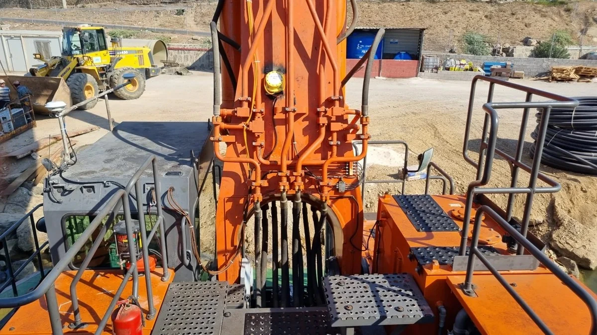 12
- 1 Kordil motion sensor visible on the boom.
- 2 One of the GNSS antennas beside the cab.
Boom, stick and bucket sensor assignments are defined during installation. A loose bracket or impact requires the relevant channel to be checked again. The photograph is neither a mounting measurement nor a service wiring diagram.
Image: kordil.com, Kordil EPS product page.4.2 Kordil H4 GNSS — position and heading reference
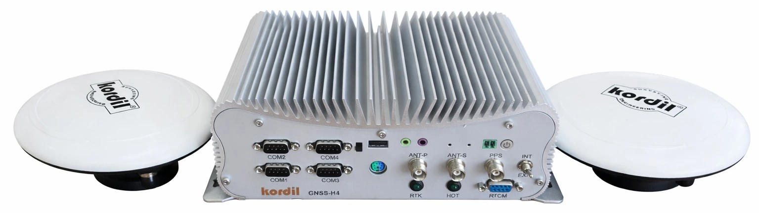
Dual-antenna GNSS position/heading solution with an integrated computer platform. Its role and connections within EPS/CPS are configured for the supplied package. H4 receiver accuracy is not the same as the overall accuracy at the bucket tip.
Product image: kordil.com, Kordil GNSS-H4 product page; 14 November 2026.Satellite visibility, multipath and correction data affect position; an unchanged antenna geometry is essential for heading. RTK corrections may arrive through NTRIP or the installed site link. Operators must check the position/heading solution status and control measurements, not just a “connected” message.
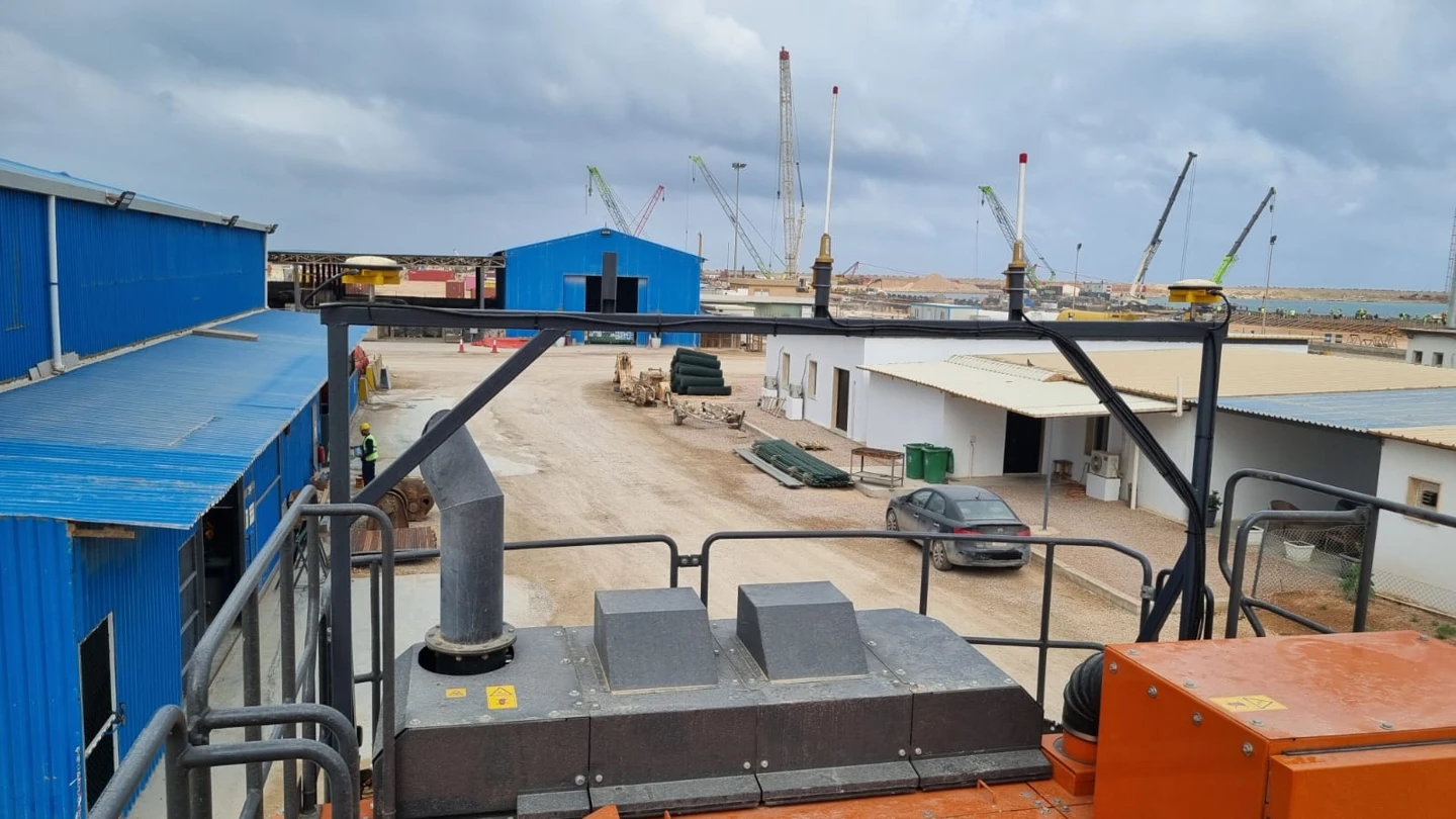 123
- 1 First GNSS antenna.
- 2 Second GNSS antenna.
- 3 Rigid support: preserve its geometry and report bending or looseness.
Distances and positions in this photograph must not be used as installation dimensions for another machine. Do not move the antennas or use their support as a load attachment or handhold.
Kordil field archive, 2026.4.3 Z sensor, rope length and cab
The Z sensoris the component measuring rope length in crane and free-fall grab arrangements. The software's Wire Length field means rope length . Interpret Z-sensor readings with the approved machine and suspension geometry. Channel names and sample display values may differ. Do not assume a counter reading is directly in metres. With slack rope, a swinging load or a grab resting on the bottom, drum payout alone does not guarantee the true vertical position of the working point.
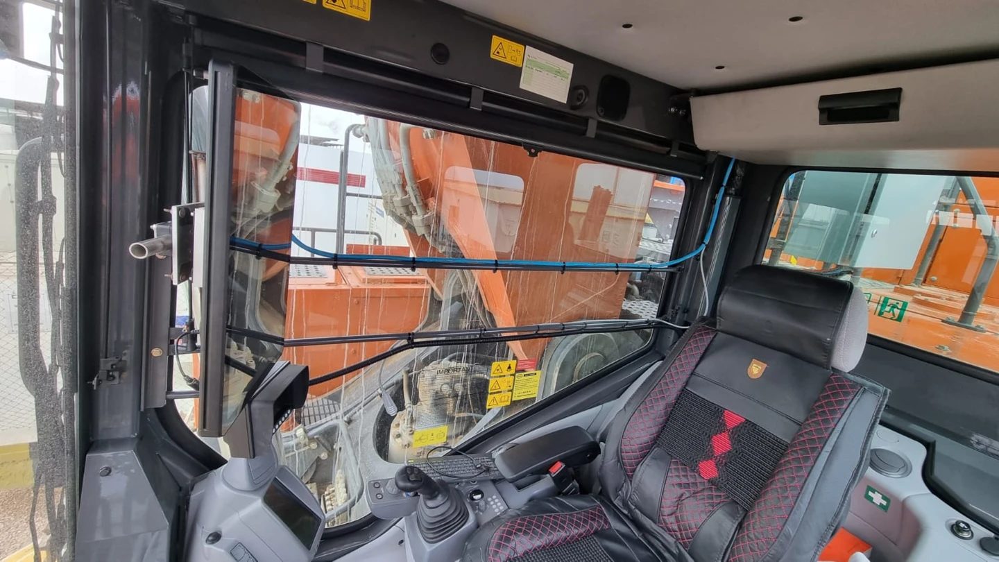
The cab display must not obstruct the operator's direct view, machine instruments or emergency controls. The Kordil sensor interface integrates the data flow. Operators must not open the interface box; power, earthing and electrical compatibility checks are for authorised personnel.
Who may change which setting?
| Role | Permitted tasks | Outside the role's authority |
|---|---|---|
| Operator | Shift checks, selecting an approved job, display settings, target tracking, recording and fault reporting | Sensor coefficients, machine geometry, reference/geodetic settings or unauthorised zeroing |
| Survey / project lead | Approved design and existing surface, coordinate/elevation definitions, control points, tolerances and record review | Uncontrolled machine movements or unauthorised electrical work |
| Kordil / authorised installation personnel | Physical installation, device assignment, geometry, calibration, testing, backups and handover | Defining design or acceptance tolerances without the project lead's approval |
| Site / lifting supervisor | Permits, lifting plan, safe zones and team coordination | Treating the position display as a safety certificate |
“Authorized” confirms an operation; it does not replace competence or a work permit. “Save and lock settings” concerns configuration persistence, not a physical safety interlock. Before changing approved settings, make a backup, record the change and define the validation plan.
From installation to the first acceptance measurement
6.1 Before arriving on site
- Identify the machine type, serial number/ID, linkage arrangement, attachment, working reach and environment.
- Obtain horizontal and vertical project references, control points, surface files and acceptance criteria.
- Verify the computer, display, sensors, GNSS and any rope-measuring equipment against the installation package.
- Arrange power supply, safe access, permits, machine shutdown and a test area.
- If replacing an existing system, safely back up its project files and settings.
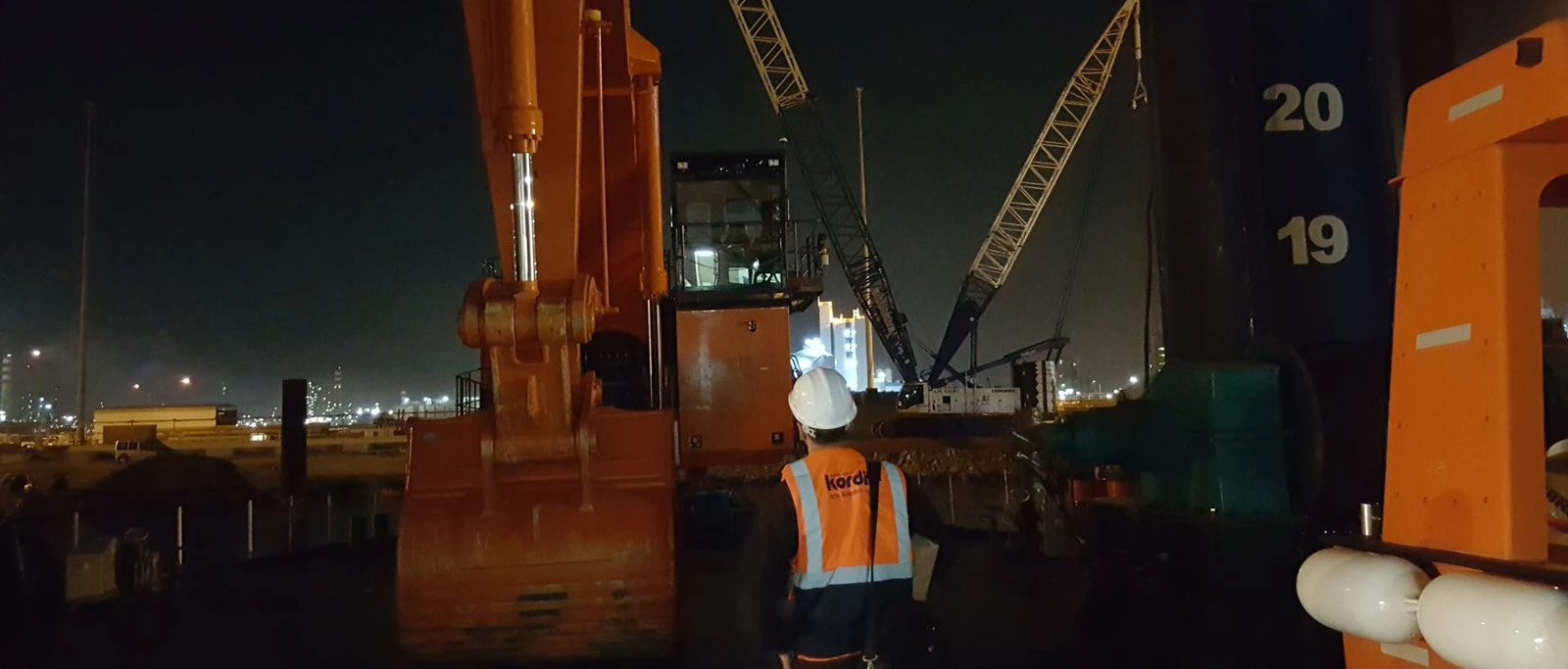
6.2 Physical installation sequence
- Secure the machine. Mechanical and electrical work must be performed by authorised personnel.
- Install sensors, antennas and cab equipment according to the approved mounting plan.
- Protect cables from joints, hot surfaces, crushing and abrasion. Check safe slack throughout the full range of movement.
- After checking power and protection, switch on the devices and match each measurement channel to its physical component.
- Define geometry and the working-tip reference, then calibrate and independently verify the system.
Connector pinouts, proprietary messages, circuit diagrams and internal sensor settings are provided only in authorised service documentation. Never short pins or wires for testing.
6.3 Software and connections
Use the approved installation package. Check that the Windows account can write to project/log folders and, for 3D view, that a suitable WebView2 runtime is available. Back up settings and projects before updating. Copying one executable alone does not necessarily update all dependencies.
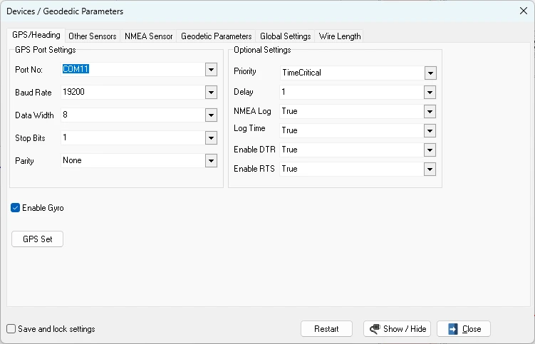 123
- 1 Port and communication settings: use only the supplied device values.
- 2 Additional options: responsibility of the installation personnel.
- 3 Saving/locking settings.
The displayed COM number and baud rate are examples, not settings to copy to another machine. Two programs attempting to use the same port can prevent connection.
Development screen archive, 1 November 2026. Tabs and fields may differ in your version.6.4 Handover items
Machine profile and attachment definition; sensor/antenna assignments; geometry and reference record; coordinate/elevation definitions; independent test results; tolerances; software version; backup copy; project/log locations; trained personnel; and authorised support channel. Installation cannot be considered complete merely because a machine graphic appears on screen.
Coordinates, elevations and water level: one reference chain
A model that looks correct on screen may be in the wrong datum. Obtain the following in writing before work: horizontal datum and projection, zone/central meridian, units, axis order, vertical datum, elevation sign convention, any geoid/local transformation, water-level source and timestamps. WGS 84 geographic coordinates and local E/N coordinates are not interchangeable.
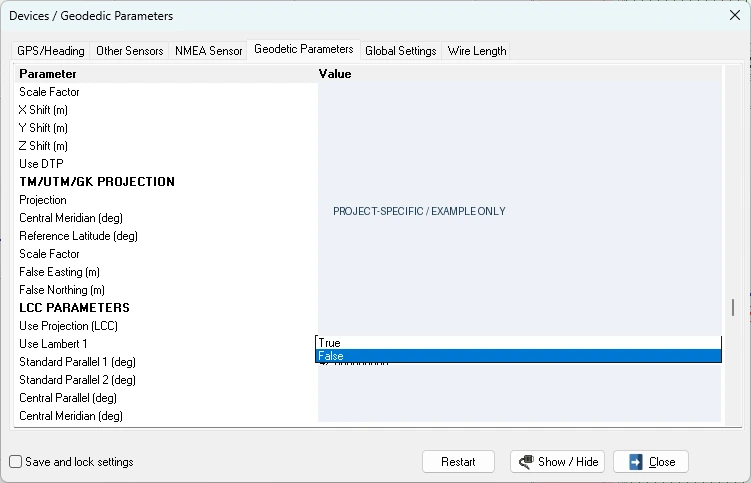 12
- 1 Check the active projection and transformation definition.
- 2 Select alternative projections only as required by the project.
Values are deliberately hidden. Validate against at least two horizontal control points and a suitable independent vertical reference. The project's acceptance plan may require more extensive testing.
Development screen archive, 1 November 2026; image prepared for training.Elevation and depth are not the same number
Elevation is a vertical coordinate relative to a defined datum; depth is a downward distance from a surface. A project target of “−10.00 m elevation”, for example, does not always mean “10 m below the water surface”. Confusing signs or references can cause work at the wrong level even while the display behaves plausibly.
Do not confuse RTK and water-level corrections
- Corrections may differ between an RTK-elevation workflow and a water-level-based workflow.
- Do not apply water level or vertical offset twice. Document where each correction is applied in the handover record.
- Record the time and source of manually entered water levels; never treat an old value as current.
- Never change “Tide Height”, “Pin Draft” or similar offsets arbitrarily to conceal a control error.
Opening projects, importing data and selecting active surfaces
8.1 Prepare the file
Retain a current, approved, read-only master copy. Place a working copy in a separate job folder. The filename should identify the job code, content and revision. Example: IS01_DESIGN_R03.xyz. Supply the coordinate/elevation system, units and boundary with the file. Design and existing survey data must not circulate under the same filename.
| Data type | Use | Before import |
|---|---|---|
| Project / .knp | Open saved drawing/job content | Check whether settings and external surfaces are also required. |
| DXF | Plan lines, boundaries and design references | Use a format supported by the installed version, such as AutoCAD R12 DXF where necessary. A line does not by itself define an elevation-bearing surface. |
| XYZ / TXT / CSV | Point data and a surface source compatible with the version | E/N/Z column order, delimiter, decimal notation, units and blank/missing values. |
| KML / KMZ | Georeferenced drawings supported by the EPS version | Verify the geodetic transformation and independently check the elevation accuracy of map content. |
| Other surface formats | Only if supported by the installed surface reader | Do not assume support from the extension alone; test a small sample. |
Your CPS version may not support every EPS import format. DXF is the basic design format published for CPS. Follow the support shown in the file dialog and the site handover instructions.
8.2 Open a project or create a new job
- If live recording is active, stop it in a controlled manner and save the current job.
- File → Open to open the correct
.knpfile, or File → New to create a new job. - File → Save As to give the working copy a new name. Do not overwrite an earlier accepted job.
- Check the machine configuration separately. Do not assume that the project file includes sensors, calibration, NTRIP and every external dataset.
8.3 Import plan data
- File → Import then select the file type and approved file.
- In supported EPS versions, select DXF, XYZ/TXT/CSV or KML/KMZ. After import, zoom to the data extent.
- Check a known point, line length and axis direction. If data appear far away, do not drag them into place; investigate coordinate or unit errors.
- Record the file revision, coverage and import result. Reloading a layer with the same name may change its content.
Points or lines visible on the map do not mean the surface used for target-elevation calculations has been selected. The layer-selection step below is also required.
8.4 Assign existing and design surface layers
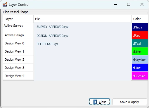 1234
- 1 Active Survey: existing/monitored survey surface.
- 2 Active Design: primary comparison design.
- 3 Design View 0–4: additional reference surfaces.
- 4 Save & Apply: apply the selection and check the result.
- Settings → Profile Layers to open the Layer Control window. If the menu location differs in your version, use the window with the same name.
- Active Survey select the existing survey/working surface. Use a writable field copy and protect the approved master file.
- Active Design select the approved design surface that defines the excavation/fill target.
- Add any required additional surfaces to Design View 0–4 and leave unused fields empty.
- Make colours and lines easy to distinguish. Colour alone does not identify a surface.
- Save & Apply to apply the settings. Check that side and cross-sections appear. Reload according to the version instructions if necessary.
- Check design elevations at several known E/N locations. Inspect slopes, breaklines and boundaries particularly carefully.
- Save the project. Record the filename, revision, active surface and check result on the shift form.
8.5 Simple XYZ example
The following fictional data illustrate column order only. For a supported reader using E, N, Z columns separated by spaces:
500000.000 4500000.000 -8.500
500001.000 4500000.000 -8.500
500000.000 4500001.000 -8.450
These three rows are not a complete project surface. Do not load a file containing headers, point IDs or commas without checking that the reader supports them. Avoid ambiguity between decimal commas and comma delimiters. A plan file without Z values does not provide a verified target surface.
8.6 Decision after import
- Are the data in the correct location, scale and elevation?
- Do the active design name and revision match the work order?
- Does the surface cover the machine point, and are there any no-data areas?
- Have tolerances and reference elevation been approved by the project lead?
- Did the known-point check pass? If not, do not begin production.
Read the plan, sections and target indicator together
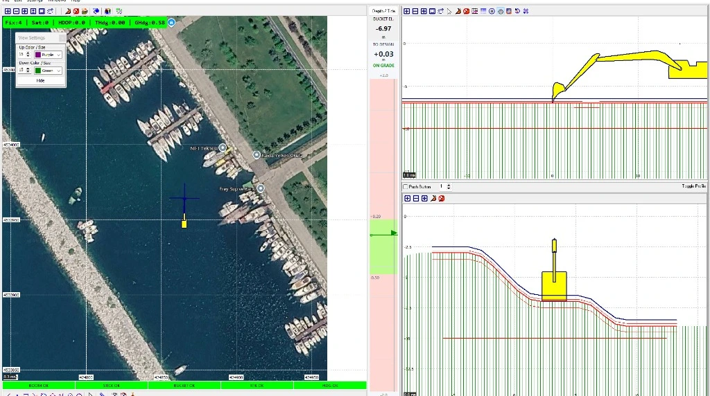 12345
- 1 Plan: horizontal position, heading and working area.
- 2 Difference to target: numeric value, direction and tolerance zone.
- 3 Side view: longitudinal profile of the linkage and working tip.
- 4 Transverse view: lateral section and relation to the design.
- 5 Sensor status bar: status of the required channels.
9.1 Plan view
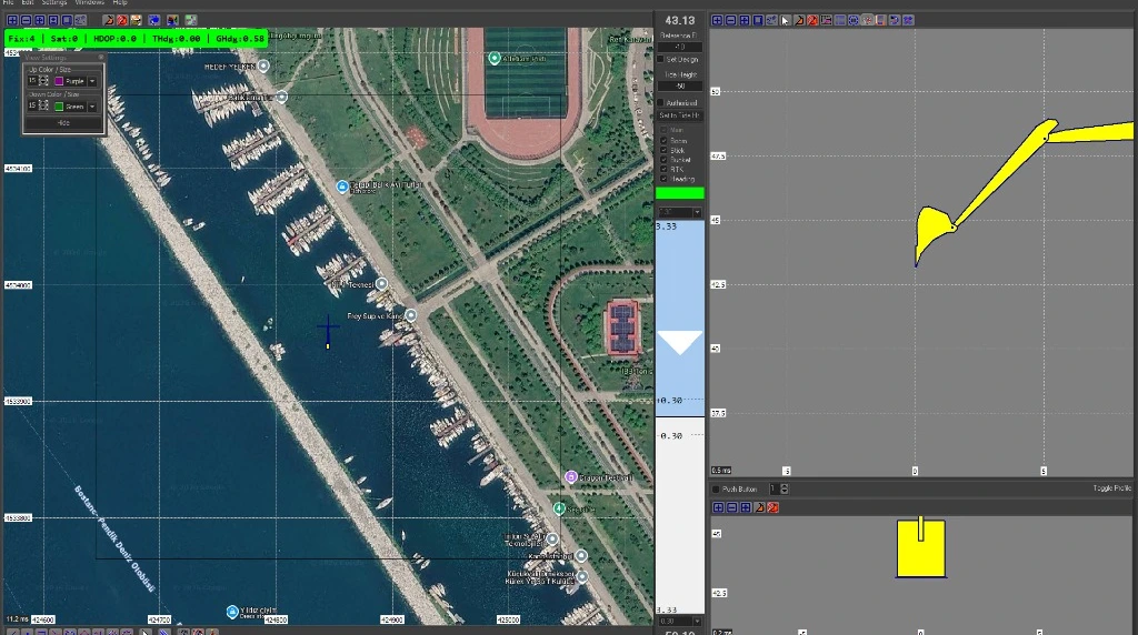
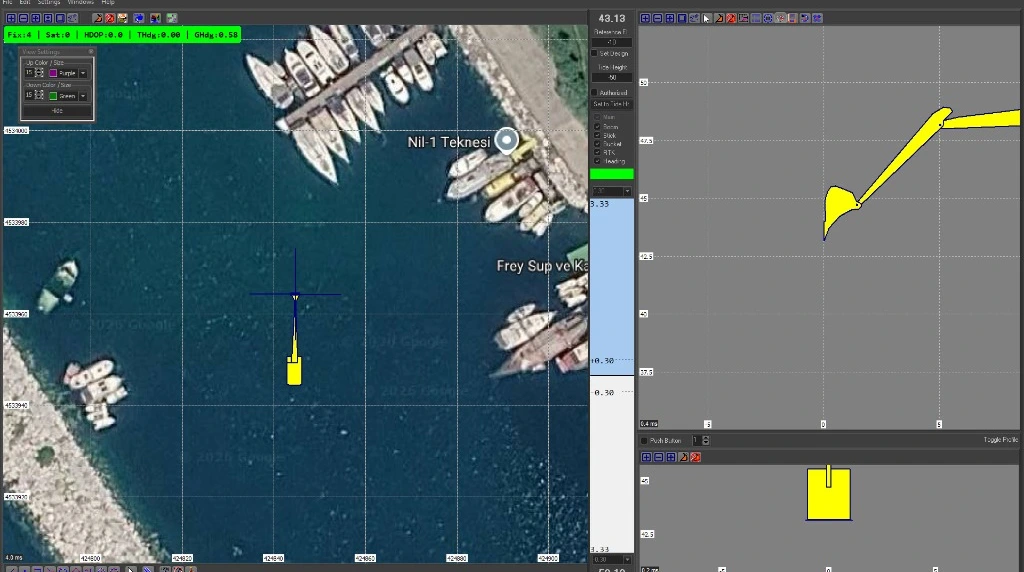
The plan is a top-down view showing the machine body, linkage, working tip, tracks, project lines and any background map. Zoom changes the view only; it does not improve measurement accuracy. Follow mode may centre the machine, while in a fixed view it can move off screen. If it is missing, check centring and coverage first.
9.2 Difference to target and tolerance
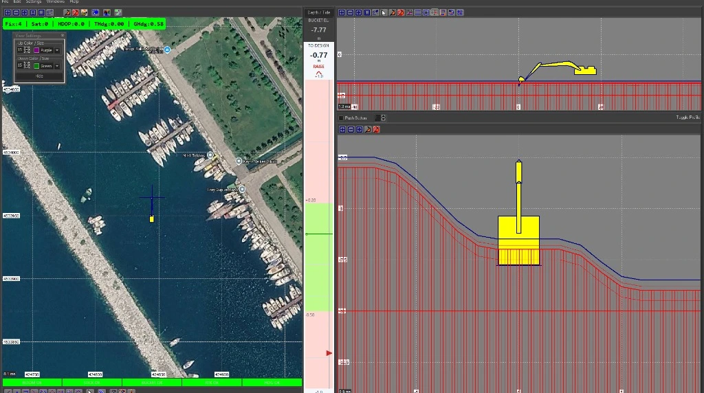
Bucket El. is the elevation of the configured working point. To Design shows the difference from the target. LOWER / RAISE / ON GRADE may describe direction and tolerance status. Signs, colours and conventions depend on version/settings and must be checked against a known elevation at the start of work. Do not simply memorise a “good” colour; read the value, text and selected surface together.
 12
- 1 This example shows a negative difference together with a RAISE warning.
- 2 Compare the working tip with the target surface in section.
This is a training scenario. Do not change the reference elevation to clear the warning; check the actual working conditions and active design.
 12
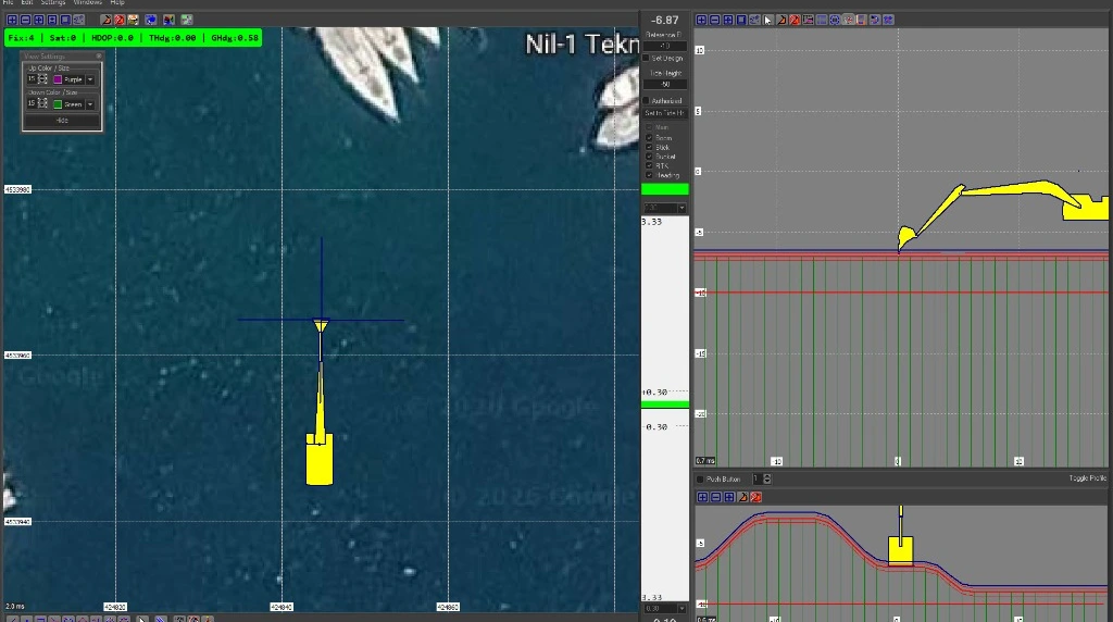
- 1 Narrow tolerance zone: defined by the project specification.
- 2 Cross-section: check the slope relationship, not only the centre point.
“On grade” does not replace independent acceptance measurements.
9.3 GNSS and the status bar
Fix indicates solution type; Sat the number of satellites used/displayed; HDOP the geometric quality indicator; THdg/GHdg and similar fields may show heading information. In standard NMEA usage, Fix 4 commonly means RTK fixed; confirm this against device configuration and version. Many satellites or a green bar alone do not prove the whole system is correct.
Assess only those body, boom, stick, bucket, wire, RTK and heading channels required by the installed arrangement. Do not mistake a disabled option for a fault, or overlook a required channel that has frozen.
9.4 Red line and different views
The red line in these examples relates to the design/target reference; line colours can be changed. A fixed reference elevation is not the same as a sloping design section. Side and front/rear views may use different scales. The positioned physical reference must remain the same; do not compare pixel heights alone. Never use old-version images as dimensional or calibration references.
Controlled production with an excavator
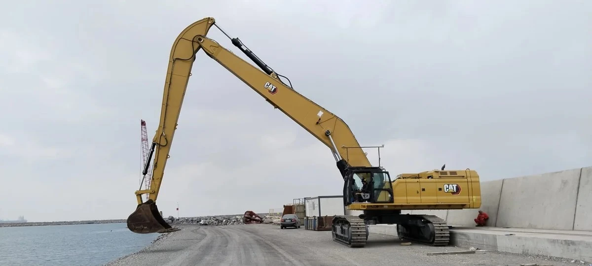
- Verify the correct bucket/attachment profile and current calibration.
- Approach the working area only when GNSS/heading and all required linkage sensors are valid.
- Check horizontal location in plan, and target elevation and slope in side and cross-sections.
- Slow down near the target. Allow for display latency, deflection and physical contact conditions.
- When recording is required, stabilise the defined contact point and machine state, then mark using the correct recording mode.
- Confirm that the mark appears in the plan/log output. Pressing the button alone is not sufficient.
- Reassess surface coverage and work boundaries when moving to a new area.
Shared precautions for filling and excavation
Distinguish under-excavation, over-excavation and acceptable areas according to project tolerances. A surface derived from bucket tracks represents points actually contacted and recorded at the correct time. Do not declare completion without checking gaps. Use both plan and section near design boundaries or breaklines.
Bucket replacement and wear
A new bucket, breaker, quick coupler or tooth can change working-tip geometry. Wear also affects the reference. Notify the authorised team and do not resume production until the approved profile is selected and independent checks are complete. An operator must not “make the picture fit” by changing an offset.
Assess crane, rope and suspension together
In CPS, the working point in plan must correspond to the physical load/suspension arrangement. “Load centre”, “hook”, “grab connection” and “cutting edge” are different points. The installation team defines the displayed point, and operators and surveyors must understand it consistently.
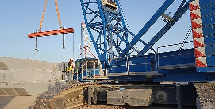
11.1 Display logic for a free-fall grab
A free-fall grab must not be treated like an articulated excavator bucket. The configured crane/winch view shows the rope and suspended grab together. Side and front/rear views must refer consistently to the same physical point. Rope length is meaningful only with the actual vertical geometry and calibration.
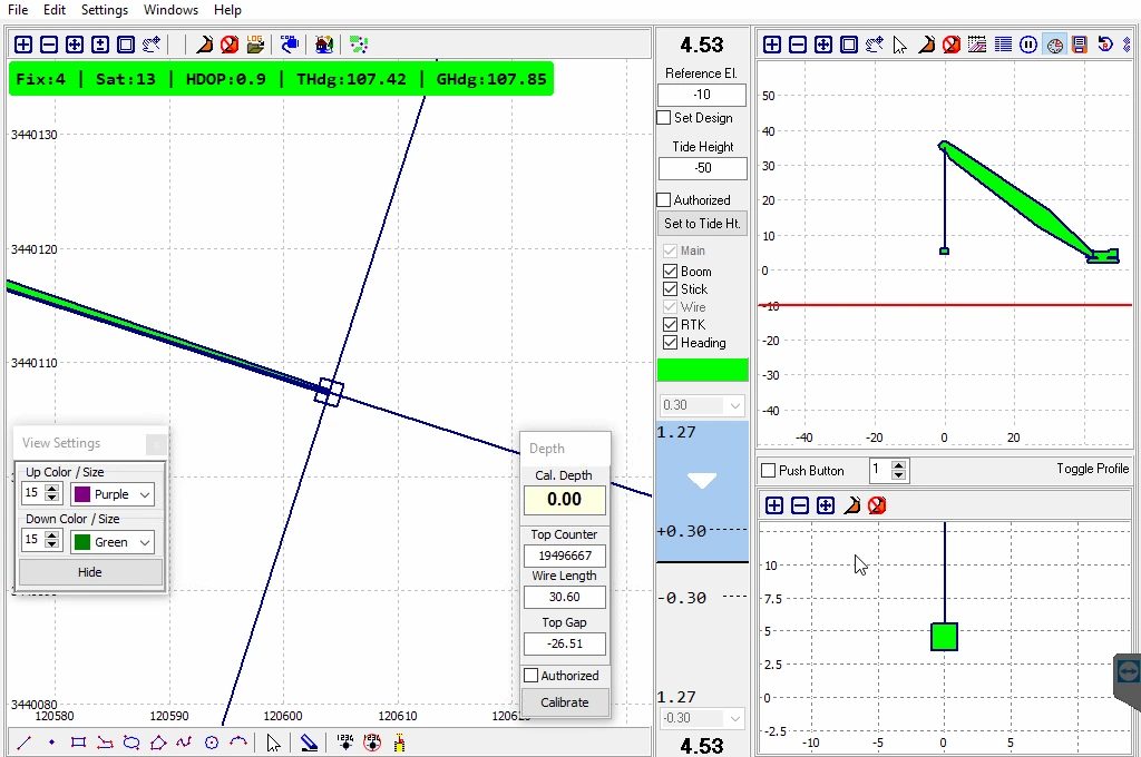 1234
- 1 Boom, rope and grab in side view.
- 2 Front/rear view of the same arrangement.
- 3 Rope-length/calibration panel: operators must not zero it arbitrarily.
- 4 Manual marking area.
In this older-version screen, the graphic scale and arrangement may differ between views. Comparing graphics is not a calibration method; use the current approved machine profile.
User-supplied application image. Water level, counter values and elevations are examples.11.2 Operating sequence
- Open the approved machine/suspension profile and verify that rope measurements are current and their direction is correct.
- Check length/elevation at a known reference position. Report any changed pulley, rope or attachment.
- Follow the horizontal target in plan view and execute the safe movement/drop plan with the site supervisor.
- When swing, rope inclination or platform motion is significant, remember that the position is only the model reference.
- Slack rope after bottom contact can separate rope payout from actual grab elevation. Account for this when choosing the recording time.
- Mark according to an independently verified procedure and check the record and surface update.
While the grab moves freely, rope measurement and the schematic alone cannot guarantee the true instantaneous cutting-edge position. The site procedure must define what records mean during falling, impact and slack-rope conditions.
11.3 Z sensor and rope length — Wire Length settings
The rope-length screen may include enable, message-recognition, scale and correction fields. Authorised installation personnel verify these settings against the device and mechanical arrangement. This public manual does not include proprietary message strings, counter coefficients or service connections. Do not change the communication format for experimentation.
Manual marking and automatic recording
In Manual/push button mode, the operator requests a record using a button, pedal or on-screen control. In Auto Dredging mode, recording requests repeat at the selected interval. Automatic recording is not automatic excavation or crane movement.
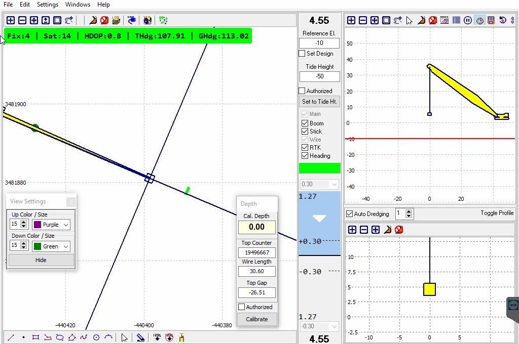 12
- 1 Auto Dredging: periodic marking selection.
- 2 Recording interval: set by an authorised procedure according to the job and machine speed.
Leaving automatic recording on while carrying material or with the working tip in the air can insert invalid points into the surface. After stopping, confirm that no new marks appear.
Initial button test
- Ensure live data are valid and the correct project is selected; identify a safe test point.
- Press once and observe the mark and corresponding log event.
- Before a second mark, confirm the first operation has completed. Do not assume very rapid presses are individually stored in a permanent queue.
- Compare button-press and recording times. If one press produces multiple marks or none, resolve the issue before operation.
Marking completes within the application's normal data/recording cycle. Do not assume each press enters an independent unlimited queue. Confirmation is the actual appearance of the mark/record.
End of shift
- Disable automatic recording and take any required final manual mark.
- Save the project. Check the date and job ID of the relevant log folder.
- Back up event logs, the working surface and any exported data separately.
- Confirm files are not empty and check several sample rows for consistency.
- Note any invalid data interval and its cause; do not delete it silently.
- Close the software in a controlled manner, then shut down the system according to site instructions.
File → Export provides export formats depending on the version. A drawing export is not a full backup containing surfaces, raw sensor logs and all settings. Open Log Folder opens the recording location if available. Clearing marks on screen does not establish whether file records have been deleted or retained; back up first.
Calibration changes settings; validation tests the result
Calibration defines the relationship between the system and the physical machine. Validation independently confirms that the settings produce the required result. Using the same point for adjustment and acceptance is insufficient. Test results across different reaches, angles, headings and required working conditions.
 123
- 1 Boom & Stick: measured reference positions.
- 2 Bucket: controlled vertical/horizontal references.
- 3 Heading: independent direction/coordinate check.
Geometry, proprietary results and site coordinates are not published. Visible example fields are not calibration values to copy. Use only for machine arrangements containing the relevant sensors.
Development archive, 30 October 2026; cropped to show user controls only.13.1 Calibration prerequisites
- Machine secured; pins, bucket and sensors sound; antenna geometry fixed.
- Correct machine profile, attachment and physical reference defined.
- Suitable survey equipment and control points; stable GNSS/heading solution.
- Previous settings backed up; measurement form and acceptance tolerances ready.
- Agreed movement and communication procedure between operator and test personnel.
13.2 Excavator check sequence
- Geometry: measure body, boom, stick and bucket references using the authorised method; verify the selected profile matches the real machine.
- Channel/movement: move each component slowly and separately to verify that boom, stick and bucket data follow the correct part.
- Boom and stick: check at safe, known reference positions using independent elevation/position measurements, then apply the appropriate calibration function.
- Bucket: safely establish the required vertical/horizontal reference positions. Verify the sensor and tip model together.
- Heading: check machine/linkage heading against independent directions or coordinates.
- Apply: save the approved corrections. Never offset other channels to compensate for a fault in one channel.
- Independent test: verify at different reaches and headings using control points not used for calibration.
13.3 CPS / rope-length check sequence
- Define the working point: suspension connection, grab cutting edge or another point?
- Test that displayed rope length changes smoothly and in the correct direction during lowering and lifting.
- Take independent measurements at several safe, known lengths/elevations. Do not test only one end of the working range.
- Use “Cal. Depth”, “Calibrate” or similar functions only with a verified reference, correct sign and proper authority.
- Check repeatability when moving up and down and the effects of rope, drum and pulley conditions.
- Define swing and slack-rope conditions and teach operators when a record is acceptable.
13.4 Interpreting results
A constant difference may indicate a reference/offset or geometry issue; reach-dependent change may relate to angle/geometry; heading-dependent differences may involve heading/body alignment. These are diagnostic clues, not definite causes. Verify the measurement conditions first. Correcting one number does not validate the whole system.
Do not use GNSS or sensor precision stated in a brochure as the field acceptance tolerance for the complete bucket/load system. Overall performance depends on reach, deflection, attachment, reference, installation and working conditions.
Test matrix and return to work
| Test | Method | Acceptance / record |
|---|---|---|
| Position and elevation | Measure the displayed working point independently at known control points. | Within approved horizontal/vertical tolerances; observations and differences recorded. |
| Heading | Repeat against a known direction and at different rotations. | Within project heading tolerance; variable differences investigated. |
| Movement / geometry | Short, medium and long reach with different safe linkage positions. | The full working range is represented; out-of-scope conditions are defined. |
| Rope length | Lower and lift at several known lengths. | Direction, scale and repeatability consistent; slack-rope limit understood. |
| Button / automatic recording | Single marks, repeated marks, automatic start/stop. | Expected records present in the file; no unintended records. |
| Data interruption | An authorised person simulates data loss in a safe test. | The operator recognises invalid/frozen data; a safe-stop procedure exists. |
| Restart | Shut down and restart in a controlled manner; check the same project and settings. | Correct profile and data restored; repeat recording test successful. |
Do not pull live connections arbitrarily for testing. An authorised person must define the interruption test. Any unacceptable result stops the work. Record adjustments/changes, retesting and approval.
Acceptance form contents
Date/time, machine and attachment IDs, software version, machine profile, project revision, horizontal/vertical reference, checking instrument, test conditions, expected/measured E/N/Z, differences, tolerance, pass/fail, tester and approver. “Looks good” is not an acceptance result.
Use difference maps and 3D models correctly
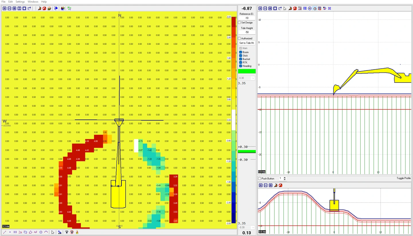 123
- 1 Cell differences: relationship to selected surfaces and sampling.
- 2 Colour scale: check range and sign convention.
- 3 Sections: geometric meaning of the difference.
First check which two surfaces the difference view compares. Changing the colour range can assign a different colour to the same difference. Cell size affects detail and processing load; smaller cells alone do not mean more accurate measurements. Do not interpret no-data areas as acceptable elevations.
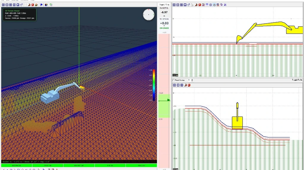 12
- 1 Relationship between model, machine and working surface.
- 2 Sections of the same job for checking target elevations and slopes.
Camera position, perspective and any vertical exaggeration can affect perception in 3D. Do not accept elevations by appearance alone. Check whether design, survey or current records are displayed. Satellite/map imagery provides visual context, not guaranteed surveyed accuracy for shores, structures or lines.
If 3D does not open
First check that 2D views and data work. Then have authorised personnel check WebView2, graphics support and required files. Do not alter sensor calibration merely to fix a 3D issue while data recording is working correctly.
Maintenance, changes and backups
Every shift
- Inspect sensor housings, brackets, antennas and visible cables from a safe position.
- Report looseness, impact, water ingress, overheating or crushing.
- Clean the display using a suitable method; keep ventilation clear.
- Perform control-point and recording tests; back up projects and logs.
Periodically or after an event
Repeat relevant calibration/validation after bucket, tooth or attachment replacement; pin or linkage repair; sensor/antenna removal; cable replacement; pulley/rope changes; impact; transport; software/configuration updates; or reference changes. Intervals depend on site risk, workload and the handover plan.
Settings may remain stable in a sound, unchanged installation, but daily visual inspection and independent verification are still necessary. Impact or geometry changes require reassessment.
What should a backup contain?
Project/drawing, active and additional surfaces, required machine settings, shape/attachment files, logs, calibration/acceptance forms and software version information. Settings containing confidential connection details must be access-controlled and never placed in public shares or on the web.
After updating, first run a controlled test and then an independent point check. If problems arise, use the approved rollback procedure. Do not mix old and new settings through ad hoc file copying.
Do's and don'ts
Do
- Select the correct machine and attachment.
- Verify the design revision in writing.
- Check GNSS, heading and sensor freshness together.
- Measure a known point at the start of work and after changes.
- Account for slack rope and load swing when deciding to record.
- Check recording mode and actual file output.
- Note suspect data periods with their times.
- Manage setting changes with a backup, justification and test.
Do not
- Do not treat the display alone as proof of safety or acceptance.
- Do not copy coefficients, offsets or port settings from another machine.
- Do not alter datum or water level to reach the target.
- Do not short communication pins or open interface boxes.
- Do not leave unnecessary automatic recording active during transport or while the tip is in the air.
- Do not continue moving when the tip position freezes.
- Do not delete faulty records without an audit trail.
- Do not publicly share calibration or support files.
Troubleshooting: symptom → check → decision
Secure the machine first. Do not change several settings at once to resolve a fault. Record whether each step changes the result. Do not return to precision work if the fault remains unverified.
| Symptom | Safe initial check | Next step / action to avoid |
|---|---|---|
| No position / invalid RTK | GNSS power/status, antenna sky view, connection and correction source. | Check whether another program is using the port. Do not alter geodetic settings randomly; seek authorised support. |
| Machine in the wrong location | Project, units, datum, zone, axis order and known point. | Do not drag the drawing to conceal the error. Verify the transformation with the survey lead. |
| Elevation consistently wrong by the same amount | Vertical datum, physical measured point and duplicate water-level/offset correction. | Do not calibrate at random. Isolate the cause using an independent elevation. |
| Error grows with reach | Correct attachment, geometry, sensor/pin condition and tests at different reaches. | Authorised geometry/angle check. Do not try to correct the full range with one vertical offset. |
| Error changes when rotating | Heading, antenna support and body reference. | Test against a known direction; revalidate if antenna positions changed. |
| A linkage component moves backwards / is frozen | Relevant sensor status, visible damage and physical channel assignment. | Stop work; have an authorised person check the channel and mounting. |
| Rope length is unchanged / jumps | Is the device enabled, is data current and is there visible mechanical damage? | The authorised team distinguishes communication faults from mechanical measurement issues. Do not zero the counter randomly. |
| No mark when the button is pressed | Live data, project/surface selection, mode, write permission and log output. | Make one safe test press. Do not open another port program simultaneously or experiment with cables/pins. |
| Multiple marks from one press | Is automatic mode on, is the button/pedal stuck, and what are the event times? | Send sample times to support. Operators must not change communication or service settings. |
| Design is not visible | Active Design file, access permissions, coverage, elevation and Save & Apply. | Do not mistake imported plan data for an active surface; test with a small verified sample. |
| Side/front views inconsistent | Machine profile, physical reference, zoom/scale, version and data freshness. | Do not calibrate to match the picture. Check a known point and the current version. |
| 3D blank / fails to open | Do 2D and surface data work? Is the required runtime installed? | Have authorised personnel check graphics, WebView2 and files. |
| Settings lost after restarting | Saving/locking, correct program shortcut and user write permissions. | Rule out an incorrect installation folder or configuration. Do not recalibrate everything. |
| No log file | Recording mode, folder, date/time, free space and write permissions. | Points on screen are not proof of a file record. Verify a new test recording in the file. |
| Slow interface | Surface density, display options, free space and background load. | Back up data/settings before authorised optimisation. Do not disable security software. |
Information to include in a support request
Machine/attachment ID; software version; fault time and time zone; reproduction steps; expected/actual result; sensor and GNSS status; latest change; relevant log interval; and a screenshot with confidential fields obscured. Never share passwords, licence keys, remote-access links or sensitive project coordinates in public channels.
Shift and handover checklists
Checkbox selections are temporary and clear when the page reloads. If an official record is required, print the completed form or transfer it to the job's record system.
Start of shift
End of shift
Field Check Record
| Job / revision | ............................................................ |
|---|---|
| Date / time / operator | ............................................................ |
| Machine / attachment / profile / version | ............................................................ |
| Control point / reference | ............................................................ |
| Expected E / N / Z | ............................................................ |
| Observed E / N / Z | ............................................................ |
| Difference / tolerance / result | ............................................................ |
| Note / corrective action / approval | ............................................................ |
Terms and frequently asked questions
| Term | Meaning |
|---|---|
| Boom | The main member rising from the machine body. |
| Arm / stick | The second linkage member between boom and bucket. |
| Bucket / teeth | Bucket / cutting tooth; the displayed reference point is defined during installation. |
| Heading | The heading of the machine/antenna system, not necessarily its direction of travel. |
| IMU / motion sensor | A sensing component contributing attitude/motion information for a part in the installed arrangement. |
| GNSS / RTK / NTRIP | Satellite positioning / precise corrected solution / network delivery of correction data. |
| E / N / Z or H | Easting / northing / elevation relative to the defined reference. |
| Survey / design / DTM | Existing/measured surface / target surface / digital terrain model. |
| Wire length / rope payout | Rope length monitored by the Z sensor; not unconditionally equivalent to the true vertical load position. |
| Calibration / verification | Calibration adjusts the relationship; verification tests the result through independent measurement. |
Can I start work if the display is green?
No. The correct project, reference, profile and control measurement must all be verified. Colours can be changed, and a valid sensor connection does not prove correct geometry.
Is a surface generated from bucket points final bathymetry?
Not automatically. It is a working/progress record dependent on recording time, contact point and sampling coverage. Apply the project's independent survey and quality plan for final acceptance.
Does Auto Dredging move the machine automatically?
In this manual, Auto Dredging means periodic recording/marking. Hydraulic movements, excavation and lifting remain under operator control.
Is every request saved if I press repeatedly?
Do not assume an unlimited permanent queue. Check that the operation completes and the mark is written to the file. Verify the required recording rate through field testing.
Is a check needed after refitting the same bucket?
Mounting, pin play, teeth or the reference may have changed. Do not resume precision work until the approved profile and control measurements have been verified.
Can I use a shoreline in satellite imagery as the target boundary?
Do not substitute it for an approved surveyed design. Background imagery differs in date, positional accuracy and licensing conditions.
Can I use this manual's values on my machine?
No. Images show different dates and test conditions. Ports, counters, offsets, water levels, tolerances and coordinates are examples.
Scope, sources and version note
Document: Kordil EPS/CPS Integrated User and Field Manual, English edition of the Turkish original, release 1.0, 14 November 2026. This is a public operational guide for operators and field teams, not an authorised service or manufacturing document. Use it with the installation contract, machine safety manual, project specification and approved site procedures.
Images were selected from user-supplied application screens, Kordil's 2025–2026 field photograph archive, the 2026 development screen archive and official product pages. Older screens explain workflows. Unrelated desktop areas were cropped, and some paths, values and results were visibly masked for training. Sensor positions were not labelled where they could not be verified from a photograph.
Official product sources
- Kordil EPS — system, components and applications
- Kordil CPS — crane positioning and field applications
- Kordil GNSS-H4 — position and heading system
- Kordil EPS — official application gallery
Product scope and options depend on the order/installation package. Rather than numerical accuracy claims, this manual relies on independent, site-specific acceptance tests. Third-party map/satellite imagery remains subject to its own rights and terms of use.
Proprietary protocols, sensor internals, algorithms, service connections, calibration coefficients, calculation formulas, passwords and licensing details are excluded from this web package. Photographs explain exterior appearance and operational checks; they are not reverse-engineering material or dimensioned installation drawings.